
Fixing structure for slide way type cooker hood

A range hood and fixed structure technology, applied in the direction of oil fume removal, heating methods, household heating, etc., can solve the problems of excessive fixing, inconvenience, troubles, etc., and achieve improved firmness, good stability, and large force bearing surface Effect

Inactive Publication Date: 2008-06-18
金家宝工业有限公司 +4
View PDF0 Cites 6 Cited by
  • Summary
  • Abstract
  • Description
  • Claims
  • Application Information

AI Technical Summary

Problems solved by technology

[0002] With the rapid development of the economy and the improvement of the quality of life, the use of range hoods has become one of the indispensable kitchen appliances in today's families. Although various manufacturers are constantly researching and developing the structure and function of the range hood, most of the hanging and fixing of the range hood is still in the way of hook and buckle, that is, the range hood is provided with a hook hole and then hooked. On the relative position of the screw, this kind of fixing structure is to ensure that the position of the hook hole and the screw does not deviate. Most people remove the bottom plate of the smoke hood to check the position of the hanging hole and the screw, which will only increase the inconvenience and trouble of fixing. , so it is necessary to improve

Method used


Image

  • Fixing structure for slide way type cooker hood
  • Fixing structure for slide way type cooker hood
  • Fixing structure for slide way type cooker hood

Examples


Embodiment Construction

[0028] In order to understand the technical contents of the present invention more clearly, it is further described as follows in conjunction with preferred embodiments of the present invention:

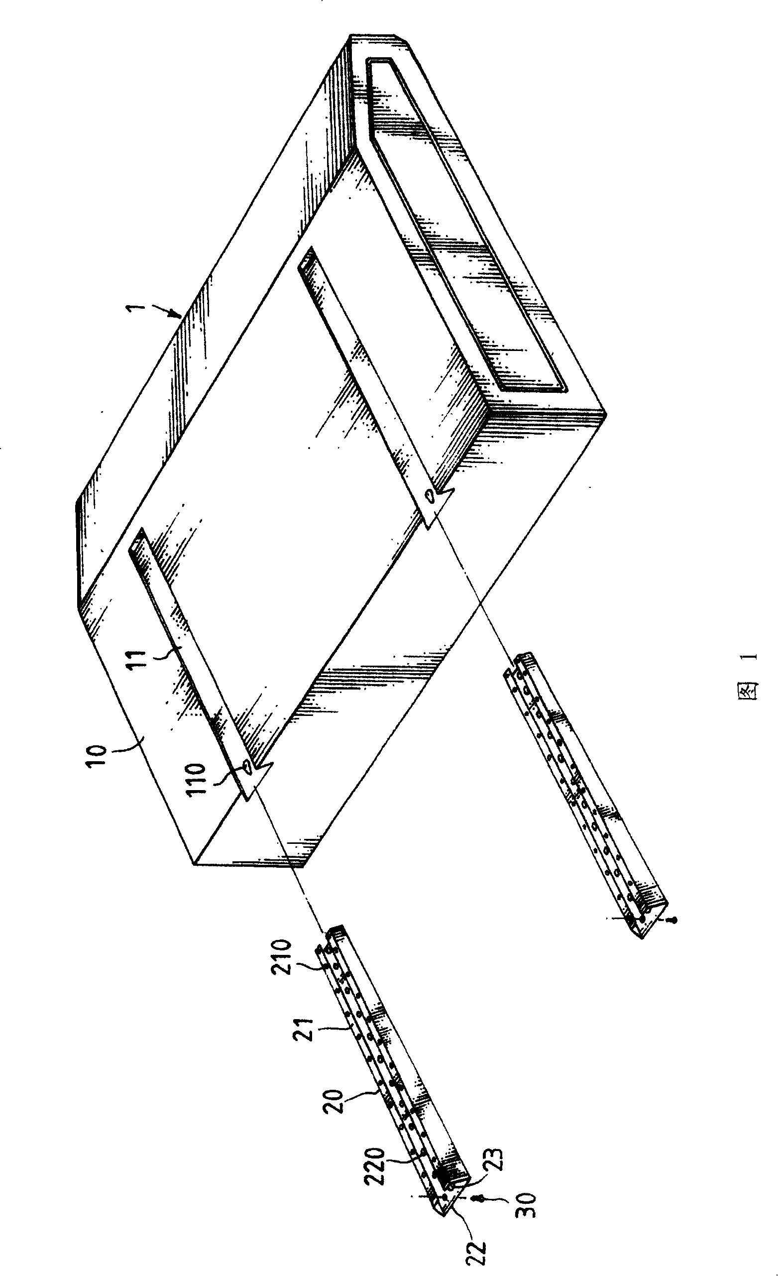
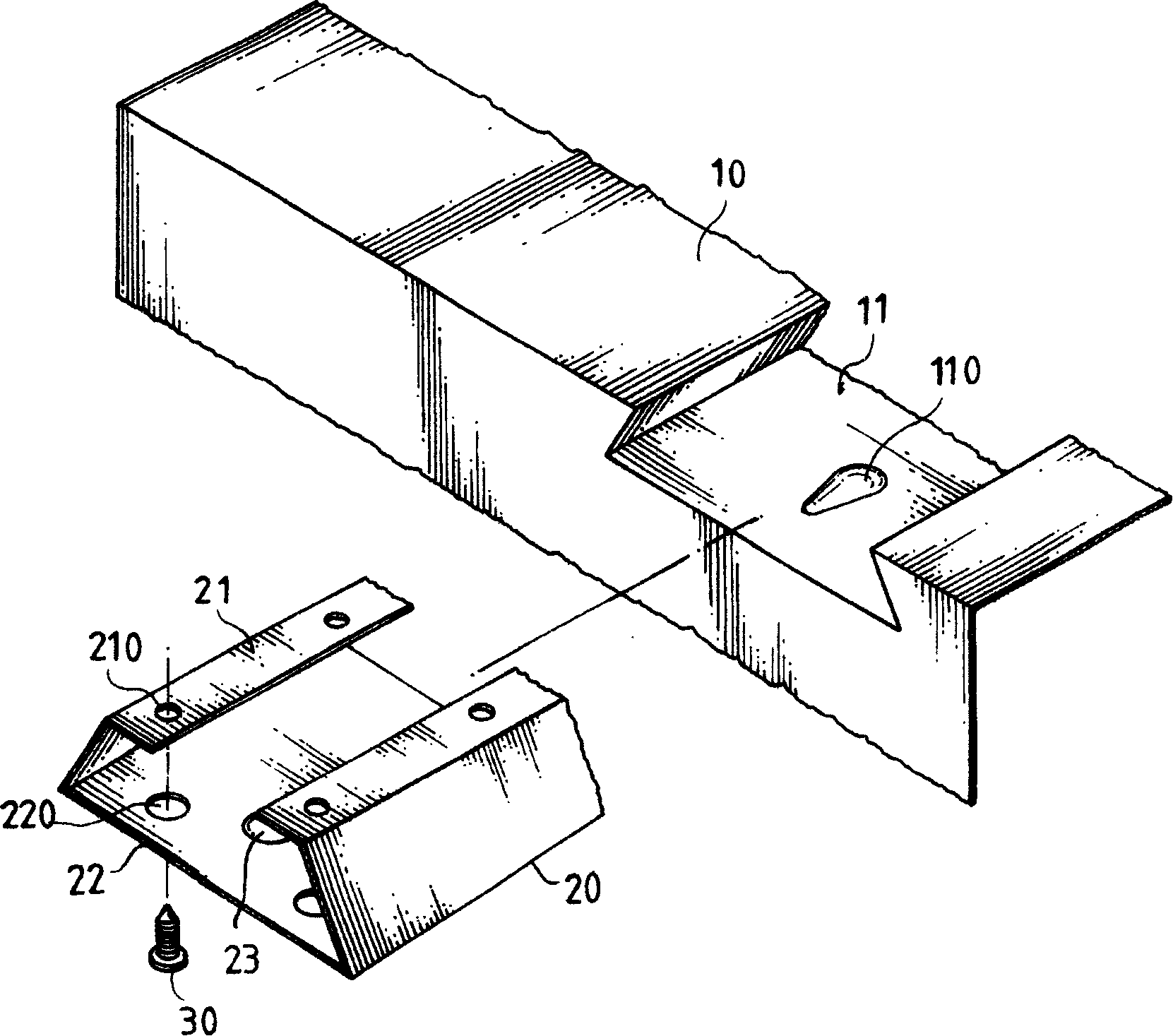
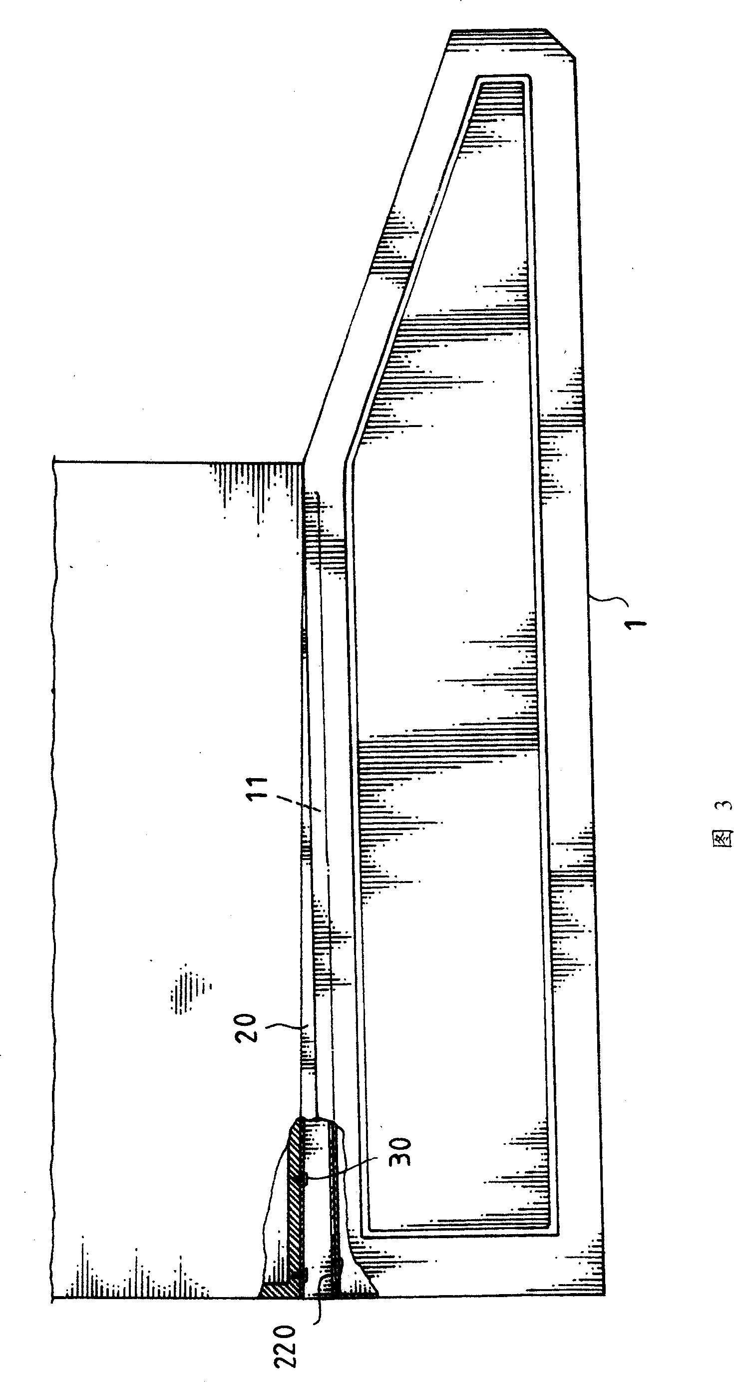
[0029] First, please refer to Fig. 1-Fig. 5, a slide rail type cooker hood fixing structure of the present invention is mainly provided with rails that can be inserted into each other on the top plate 10 of the range hood 1 and the hanging place. Groove 11 and rail 20, wherein:

[0030] The track groove 11 is in the shape of two parallel dovetail grooves with an appropriate depth. The front notch of the track groove 11 is provided with a positioning point 110, and the positioning point 110 can be a groove shape inclined downward from the front edge; The rail 20 is a dovetail-shaped bar body corresponding to the rail groove, and its top surface is provided with a horizontal folding surface 21 facing inward, and a number of rows of holes 210 are arranged on the horizontal folding surfa...


PUM


Abstract

The invention provides a trolley ventilator fixing structure which comprises rail slots arranged on a top plate or a side plate of the ventilator by integrated forming or combination and rail bars which can be mutually spliced with the rail slots and arranged at a hanging location. The rail slots have a proper depth and are arranged in parallel. The rail bars are strip bodies corresponding to the shapes of the rail slots. A front slot opening of the rail slot can be provided with a positioning point. The location corresponding to the bottom surface of the rail bar is provided with a buckling-fixing point. The top surface of the rail bar is provided with a horizontal folded surface towards the inside in an opposite shape and is provided with a plurality of discharge holes. The location corresponding to the bottom surface of the rail bar is provided with a perforation with an aperture a little larger than that of the discharge hole. The rail slot arranged on the top plate and the corresponding rail bar can be in a dovetail shape, a round shape or an elliptical shape. The rail slot arranged on the side plate and the corresponding rail bar can be in a dovetail shape, an internally concave shape, a rectangle, a round arc shape, a triangle, a round shape or an elliptical shape. Utilizing the trolley ventilator fixing structure of the invention can improve the fixing stability of the ventilator and lead the ventilator to be convenient to assemble as well as being beneficial to the exhaust of oil stain.

Description

technical field [0001] The invention relates to a fixing structure of a range hood, and more particularly, to a slide rail type fixing structure of a range hood. Background technique [0002] With the rapid development of the economy and the improvement of the quality of life, the use of range hoods has become one of the indispensable kitchen appliances in today's families. Although various manufacturers are constantly researching and developing the structure and function of the range hood, most of the hanging and fixing of the range hood is still in the way of hook and buckle, that is, the range hood is provided with a hook hole and then hooked. On the relative position of the screw, this kind of fixing structure is to ensure that the position of the hook hole and the screw does not deviate. Most people remove the bottom plate of the smoke hood to check the position of the hanging hole and the screw, which will only increase the inconvenience and trouble of fixing. , so th...

Claims


Application Information

Patent Timeline
IPC IPC(8): F24C15/20
CPCF24C15/2071
Inventor 江照政江吉雄江意文
Owner 金家宝工业有限公司
Learn More