
Portable electronic device

An electronic device and portable technology, applied in the direction of electrical digital data processing, instruments, digital data processing components, etc., can solve the problems of users' hand discomfort, general products without structure, and increased burden

Inactive Publication Date: 2008-06-18
INVENTEC CORP
View PDF0 Cites 4 Cited by
  • Summary
  • Abstract
  • Description
  • Claims
  • Application Information

AI Technical Summary

Problems solved by technology

However, if the user holds the portable electronic device for a long time to perform functions such as calling, video communication or surfing the Internet, it will easily cause discomfort to the user's hand, and when the user holds the portable electronic device with one hand, only It is very inconvenient to handle other work affairs with the other hand. Therefore, a support seat accessory is also provided on the market. When the user wants to use for a long time or watch the screen of the portable electronic device, it is used to provide Electronic devices stand and support. However, portable electronic devices are light, thin, and easy to carry as the main appeal. If you need to carry support bases and other equipment with you, it will cause inconvenience for users to carry and increase the burden on use.
[0005] This shows that above-mentioned existing portable electronic device obviously still has inconvenience and defect in structure and use, and urgently needs to be further improved
In order to solve the above-mentioned problems, the relevant manufacturers have tried their best to find a solution, but no suitable design has been developed for a long time, and the general products do not have a suitable structure to solve the above-mentioned problems. This is obviously related. The problem that the industry is eager to solve

Method used


Image

  • Portable electronic device
  • Portable electronic device
  • Portable electronic device

Examples


Embodiment Construction

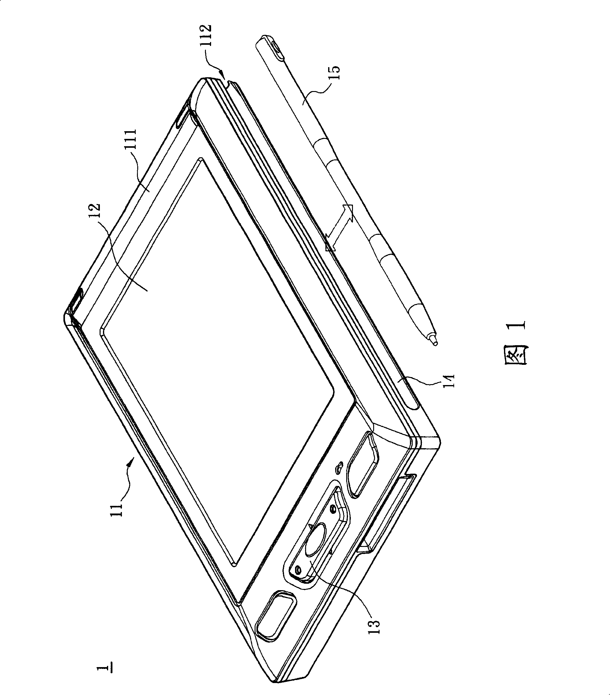
[0044] In order to further explain the technical means and effects that the present invention adopts to achieve the intended purpose of the invention, below in conjunction with the accompanying drawings and preferred embodiments, the specific implementation, structure, features and features of the portable electronic device proposed according to the present invention will be described below. Efficacy, detailed as follows.

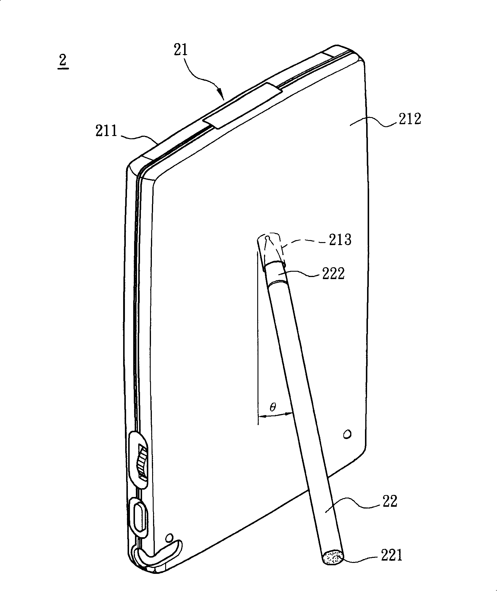
[0045] see figure 2 Shown is a rear perspective view of the portable electronic device 2 according to the first preferred embodiment of the present invention. In this embodiment, an upright portable electronic device 2 is taken as an example, but it is not limited thereto. Portable electronic devices such as slide cover, screw cover or flip cover are all included in the present invention. category.

[0046] The portable electronic device 2 includes a body 21 and a stylus element 22, the body 21 has a first surface 211, a second surface 212, a touch module...


PUM


Abstract

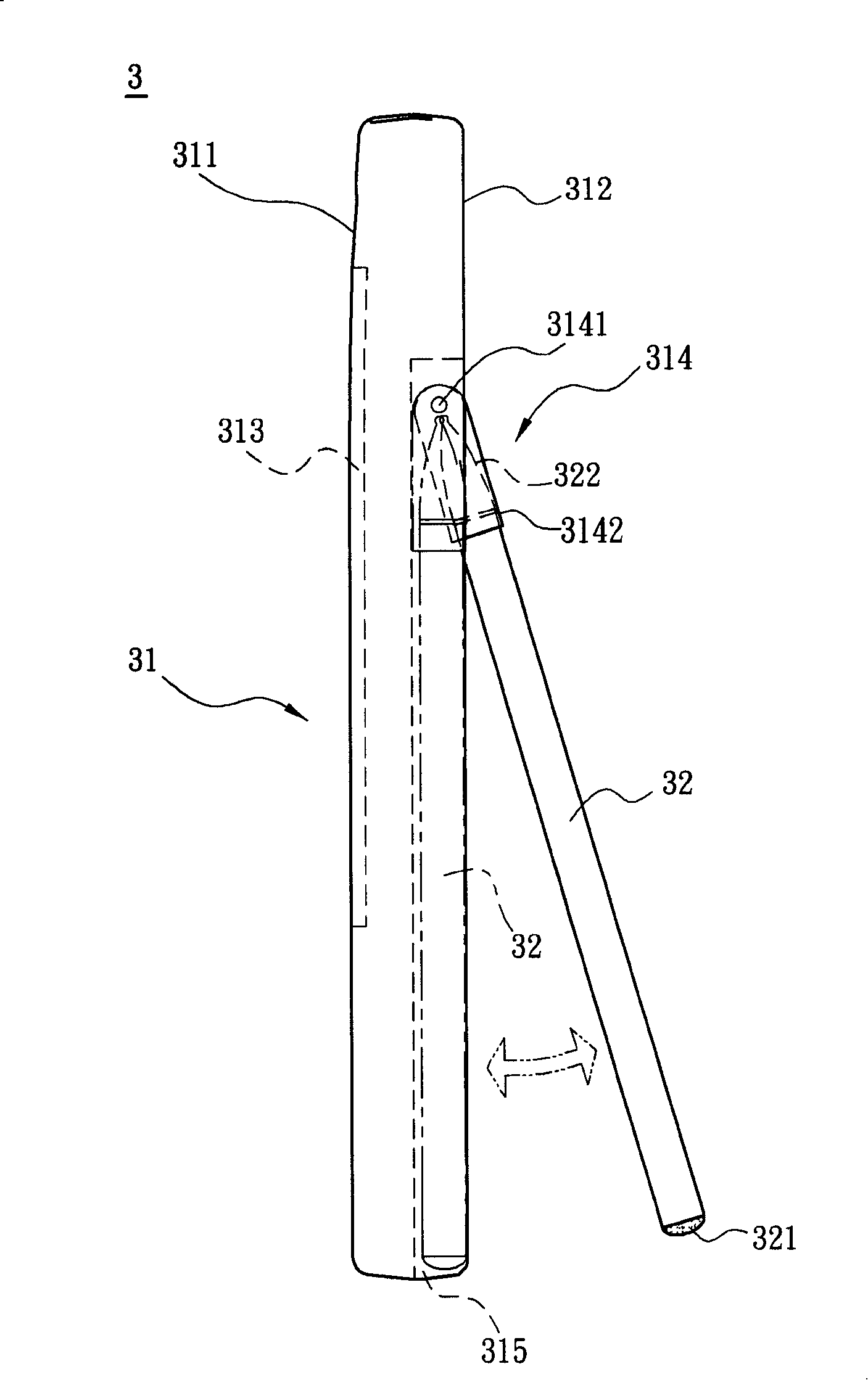
The invention relates to a portable electronic device which comprises a body and a touch control stylus component. The body comprises a first face and a second face which are arranged oppositely. In addition, the body at least comprises a touch control module and a connection part. The touch control module is arranged on the first face. The connection part is arranged on the second face and is a groove. The touch control stylus component comprises a standing part and a touch control part which are arranged respectively at two opposite ends of the touch control stylus component. When the touch control stylus component is inserted in the connection part, the touch control part is inserted in the groove. An angle is formed between the touch control stylus component and the body so as that the body can stand. The portable electronic device of the invention does not need any added device. The portable electronic device can be supported to stand on a flat only via the touch control stylus component possessed by the portable electronic device.

Description

technical field [0001] The invention relates to a portable electronic device, in particular to a portable electronic device with a supporting function. Background technique [0002] Portable electronic devices not only have the functions of light, small and easy to carry, but also because of their special man-machine interface (such as touch input interface), wireless communication (such as voice and data transmission) and artificial intelligence (such as text and Voice recognition) and other functions enable users to handle personal work affairs anytime and anywhere, and thus are widely used in various fields. Common portable electronic devices currently used in mobile communications include personal digital assistants (personal digital assistants, PDAs) and mobile phones, among which, taking personal digital assistants as an example, because current personal digital assistants have already combined the communication functions of mobile phones, Users can use the personal d...

Claims


Application Information

Patent Timeline
Patent Type & Authority Applications(China)
IPC IPC(8): G06F1/16G06F3/033G06F3/0354
Inventor 李宜扬
Owner INVENTEC CORP
Learn More