Starter

A technology of starters and motors, which is applied in the direction of engine starting, engine motor starting, electric components, etc. It can solve problems such as collision or hooking of terminal items, expansion of starter projected area, poor configuration of car body, etc., to achieve Prevents breakage and lead wire dropout, realizes configurability, and realizes the effects of product reliability

A technology of starters and motors, which is applied in the direction of engine starting, engine motor starting, electric components, etc. It can solve problems such as collision or hooking of terminal items, expansion of starter projected area, poor configuration of car body, etc., to achieve Prevents breakage and lead wire dropout, realizes configurability, and realizes the effects of product reliability

CN101203996AInactive Publication Date: 2008-06-18MITSUBA CORP

Image

  • Starter
  • Starter
  • Starter

Examples


Embodiment Construction

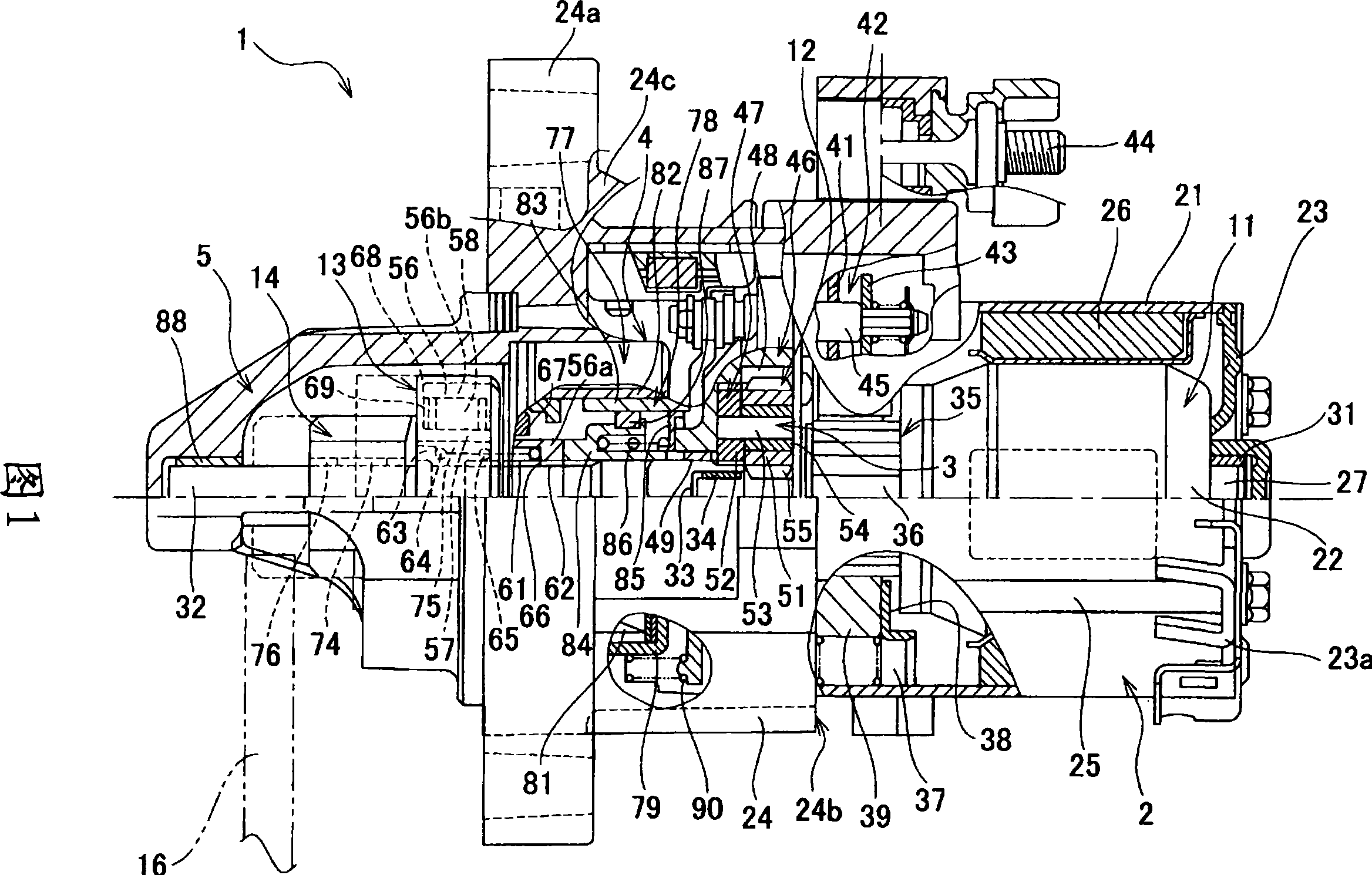
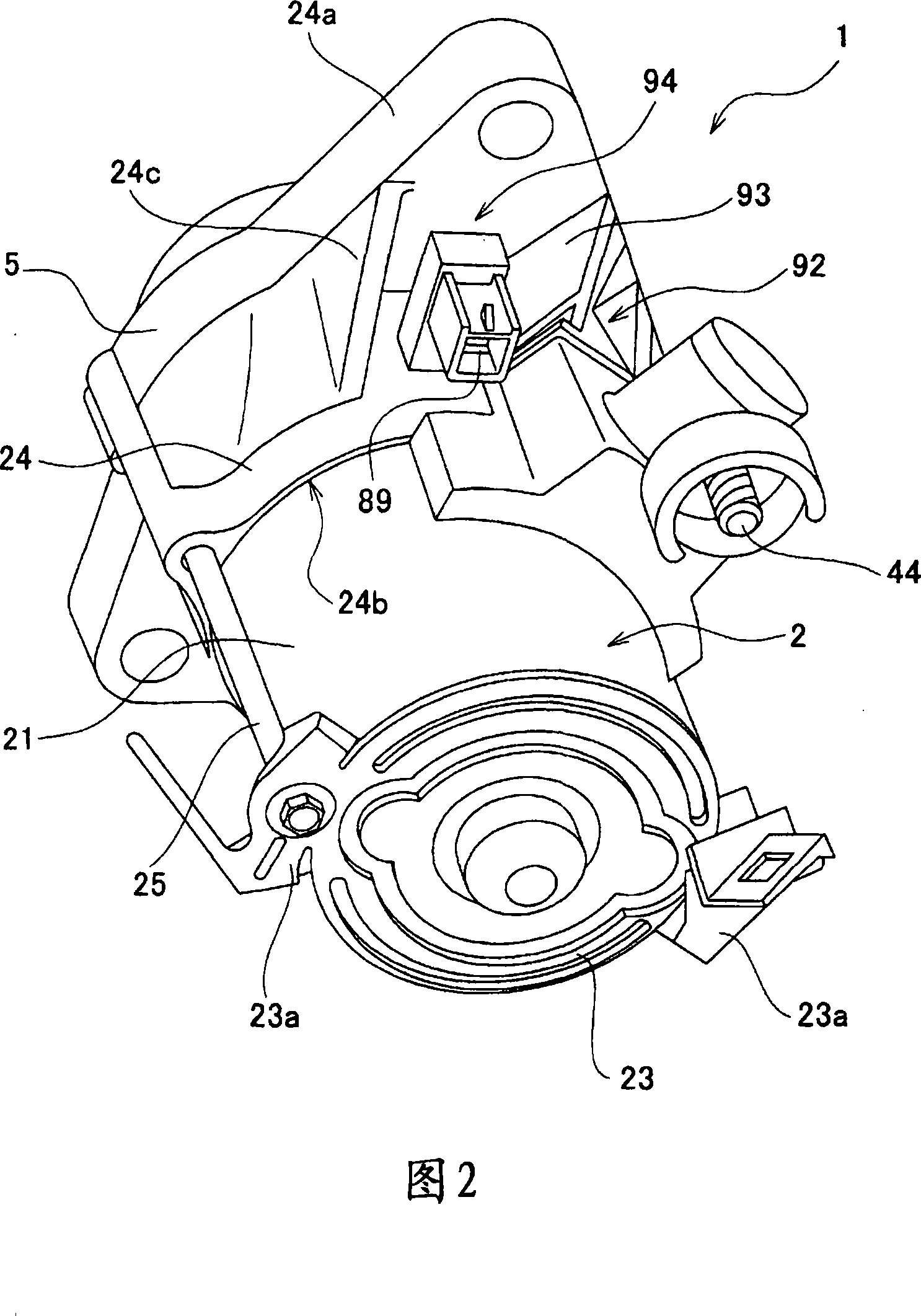
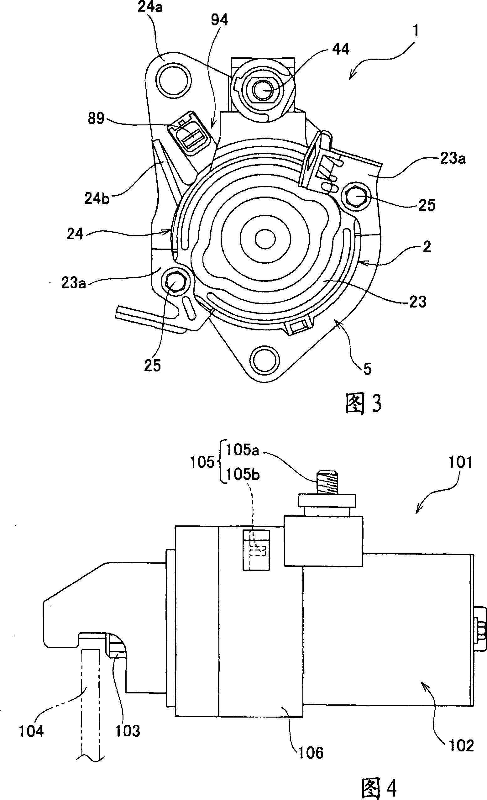
[0022] Hereinafter, embodiments of the present invention will be described in detail with reference to the accompanying drawings. 1 is a partial cross-sectional side view showing the structure of a starter according to an embodiment of the present invention, FIG. 2 is a perspective view of the starter of FIG. 1 , and FIG. 3 is a front view of the starter of FIG. 1 . The starter 1 of FIG. 1 is used for starting an automobile engine, and applies rotation required for fuel intake, atomization, compression, and ignition to the stopped engine.

[0023] The starter 1 is roughly divided into a motor unit 2 , a gear unit 3 , an auto switch unit 4 , and a case 5 . An electric motor 11 serving as a drive source is arranged in the motor portion 2 , and a planetary gear mechanism 12 serving as a reduction gear, an overrunning clutch 13 , a pinion 14 , and the like are arranged on the gear portion 3 . The pinion 14 is mounted so as to be movable in the axial direction (left-right directio...


PUM


Abstract

A starter having a motor (11) with a motor contact for controlling conduction of electricity to an armature provided in a motor housing (21), a gear cover (24) installed on the motor (11) and having a flange (24a) formed on its outer periphery, a switch terminal (89) provided outside the gear cover (24), and a magnet switch connected to the switch terminal (89). The switch terminal (89) is positioned near the flange (24a), at a portion in the area of projection of the flange (24a). A rib (24c) and a motor terminal installation section (92) are formed at the flange (24a). The switch terminal (89) is placed in a switch terminal receiving section (94) formed surrounded by the rib (24c), a sidewall (93) of the motor terminal installation section (92), and the flange (24a).

Description

technical field [0001] The present invention relates to a starter mounted on an engine of an automobile or the like and used for starting the engine, and more particularly, to a terminal mounting position of a starter rotated by an electric motor. Background technique [0002] As an engine used for an automobile, a two-wheeled vehicle, a large generator, or the like, there is generally a product in which the starting operation is performed by an electric starter mounted on the engine. FIG. 4 is a side view showing the structure of such a starter, and FIG. 5 is a front view of the starter of FIG. 4 . As shown in FIG. 4 , the starter 101 uses an electric starter motor 102, and drives the pinion gear 103 to rotate via a reduction mechanism or an overrunning clutch not shown. The pinion gear 103 is mounted so as to be movable in the axial direction, and when the starter switch is turned on, moves in the axial direction by the operation of an auto switch (not shown), and meshes ...

Claims


Application Information

Patent Timeline
18 Jun 2008
Publication
CN101203996A
IPC
H02K7/10; F02N11/00
CPC
F02N15/00; Y10T74/132; Y10T74/137; F02N11/00
Inventors
小野一志; 池守朋彦