Cutter machine and its controlled circuit and controlled method

A technology for controlling circuits and cutting plotters, applied in the field of plotting plotters, can solve problems such as huge cost, achieve high-quality work performance, simple structure, and low manufacturing cost

Inactive Publication Date: 2008-06-25
深圳市创造机电有限公司
View PDF0 Cites 9 Cited by
  • Summary
  • Abstract
  • Description
  • Claims
  • Application Information

AI Technical Summary

Problems solved by technology

However, the existing cutting plotters are either difficult to increase the cutting pressure of the cutting knife under the premise that the size of the knife seat is as small as possible, or it is necessary to spend a huge cost to modify the knife seat

Method used


Image

  • Cutter machine and its controlled circuit and controlled method
  • Cutter machine and its controlled circuit and controlled method
  • Cutter machine and its controlled circuit and controlled method

Examples


Embodiment Construction

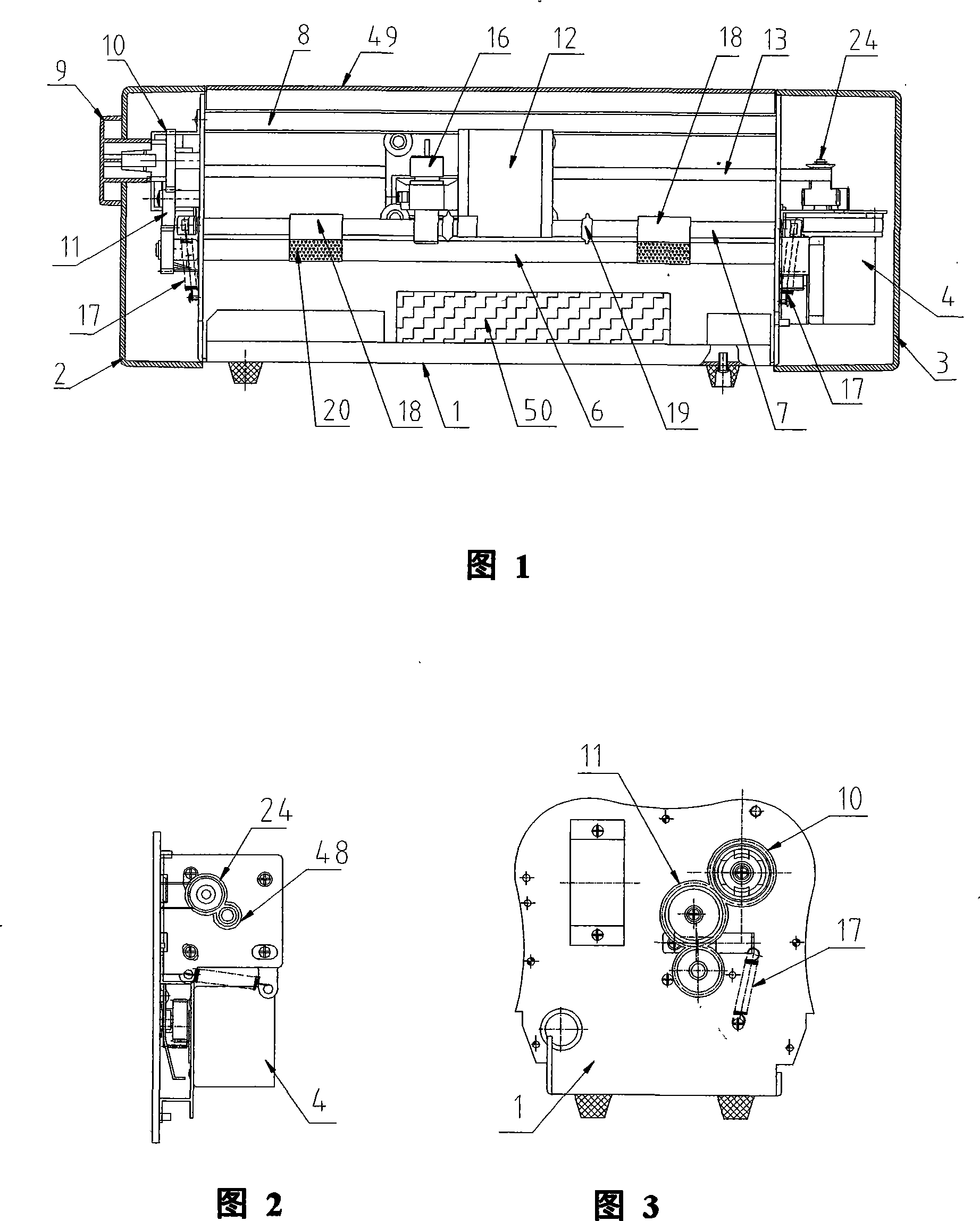
[0040] The basic structure of the new preferred embodiment shown in Fig. 1, Fig. 2 and Fig. 3, a kind of carving plotter, comprises by base 1 and is positioned at the left and right casing 2,3 of base 1 both sides and is positioned at base 1 The casing formed by the cover plate 49 above; the Y axis motor 4 and the X axis motor 5; The file to be written is read and analyzed, and then a control command is issued according to the analyzed content, and the Y-axis motor 4 and the X-axis motor 5 are driven to drive the carving knife through the transmission device to perform automatic lettering processing.

[0041] On the top of the base 1, between the left and right casings 2 and 3, there are mutually parallel paper feed shafts 6 linked by the Y-axis motor 4, a paper platen shaft 7 cooperating with the paper feed shafts 6, and a paper feed shaft 6 behind the paper feed shafts. Side beams 8. At the same time, as shown in Figure 2, a knob 9 is provided on the outer wall of the left ...


PUM


Abstract

The invention discloses a carving machine and a control circuit thereof. The carving machine comprises a base, a Y axis motor and an X axis motor; a paper moving axis and a paper pressing axis moving continuously with the Y axis motor, a racing car connected with a synchronous belt moved continuously with the X axis motor, a lower arbor connected with the racing car, a knife block arranged at the front end of the lower arbor, an electromagnetic module connected with the lower arbor and arranged in the base, a transmission mechanism, a driving control board including a control circuit arranged on the base. The control circuit comprises a central processing unit and a programmable logic cell connected with the central processing unit as well as an X axis motor driving circuit, a Y axis motor driving circuit and a nicking tool controlling circuit respectively used for generating driving by a transmitted control instruction so as to drive the racing car to move by the X axis motor in the X axis direction through the transmission mechanism at a changing speed and the synchronous belt; driving the paper moving axis to move from the front to the back in the X axis direction through the transmission mechanism at a changing speed by the Y axis motor; controlling the electromagnetic module to drive the knife block to generate lettering actions. The invention has the advantages of simple structure and high control precision.

Description

technical field [0001] The present invention relates to a plotter, in particular to a plotter which adopts a control system for precise control and has a structure for quickly adjusting the plotter and a structure for increasing the pressure of the plotter under the knife, as well as a control circuit and a control circuit for controlling the plotter. method. Background technique [0002] There are many types of cutting plotters for cutting patterns on paper media, which provide a lot of convenience and fun for people's daily work. Nowadays, the mini-cutting plotter equipment generally used in small processing workshops and households is rough in structure and poor in precision, resulting in rough patterns cut on the cutting medium, corner cutting parts and slender parts are prone to damage and breakage The situation makes it difficult for the cut plotter to meet the user's requirements. [0003] In addition, when using a traditional cutting plotter, you must first adjust ...

Claims


Application Information

Patent Timeline
Patent Type & Authority Applications(China)
IPC IPC(8): B44B3/00B44B3/06B41J3/00
Inventor 孙晓兵
Owner 深圳市创造机电有限公司
Why Eureka
Try Eureka