
Scanner lens fixation structure

A fixed structure and scanner technology, applied in image communication, electrical components, etc., can solve the problems of complicated assembly procedures, poor glue fixation, lens leakage and displacement, etc., and achieve simple and low assembly procedures and low assembly costs Effect

Inactive Publication Date: 2008-06-25
INVENTEC CORP
View PDF0 Cites 0 Cited by
  • Summary
  • Abstract
  • Description
  • Claims
  • Application Information

AI Technical Summary

Problems solved by technology

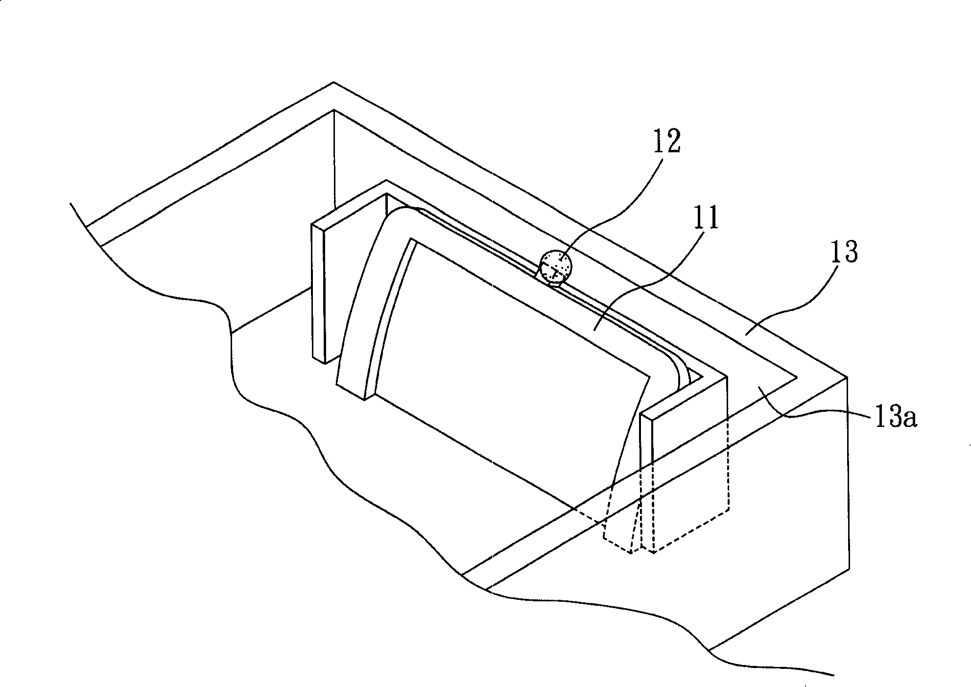
The disadvantages of this existing scanner lens fixing structure include that additional dispensing procedures must be added during the manufacturing process, resulting in complicated assembly procedures
In addition, the fixation of the adhesive is poor, and it is easy to cause the lens to leak and shift due to the temperature and humidity of use or impact
Furthermore, the lens fixed by dot glue is less stable
[0004] On the other hand, if the lens is to be fixed in the lower housing by other additional fixing mechanisms such as screws or rivets, whether the lens can withstand the damage caused by these fixing mechanisms must be considered on the one hand. The urgent force generated by the fixing, on the other hand, the complexity of the assembly process and the increased cost of the fixing mechanism must also be considered

Method used


Image

  • Scanner lens fixation structure
  • Scanner lens fixation structure
  • Scanner lens fixation structure

Examples


Embodiment Construction

[0031] The implementation of the present invention is described below through specific examples, and those skilled in the art can easily understand other advantages and effects of the present invention from the content disclosed in this specification. The present invention can also be implemented or applied through other different specific embodiments, and various modifications and changes can be made to the details in this specification based on different viewpoints and applications without departing from the spirit of the present invention.

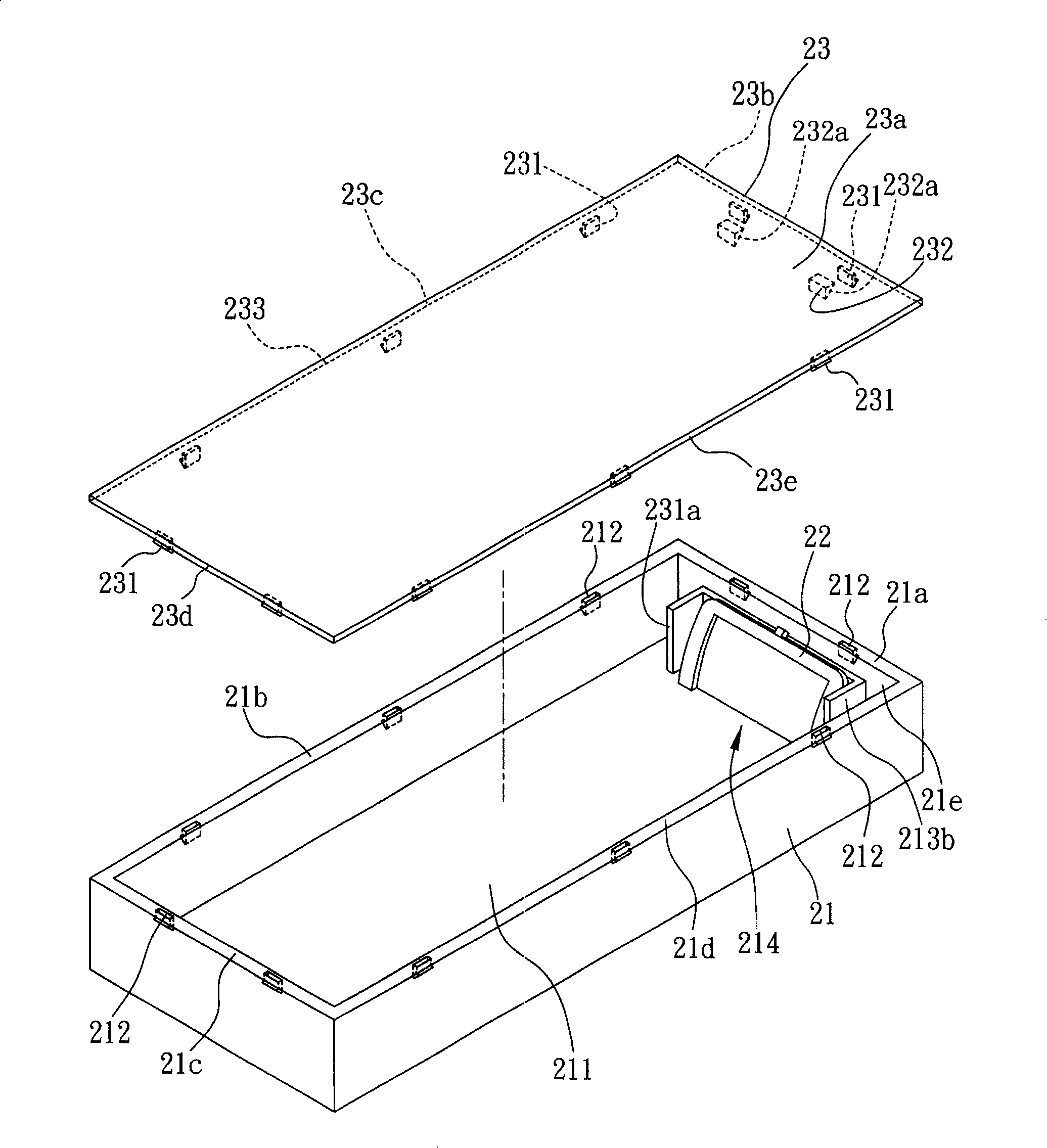
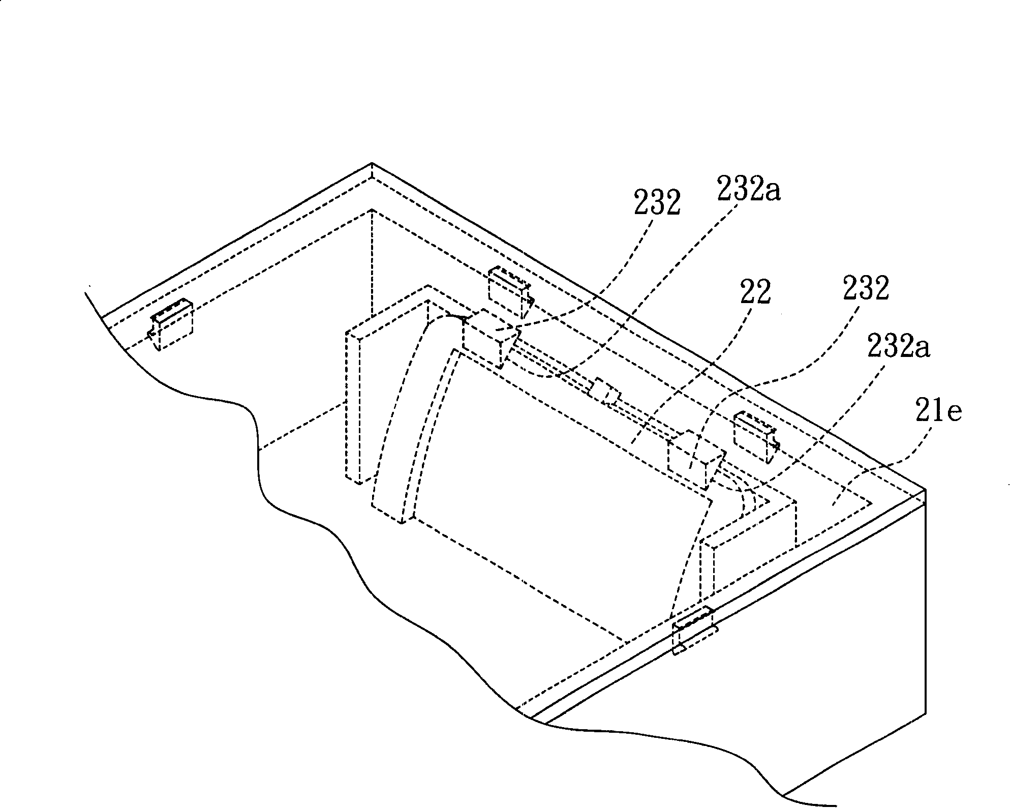
[0032] see figure 2 , which is a schematic diagram of the scanner lens fixing structure of the present invention. As shown in the figure, the scanner lens fixing structure of the present invention includes a lower casing 21 , a lens 22 and an upper cover 23 .

[0033] The lower casing 21 has an accommodating space 211 and an engaging portion 212 . This accommodating space 211 is used to place other mechanisms required by the scanner,...


PUM


Abstract

The invention discloses a scanner lens fixing structure, which comprises a lower casing which is provided with a holding room and a gripping-connecting part, a lens which is arranged at least one side surface inside the holding room of the lower casing, and an upper cover body which has a gripping-connecting piece, the gripping-connecting piece corresponds to a gripping-connecting part and is used to grip and connect with the gripping-connecting part mutually; the upper cover body also has a fixing part which is arranged at one side surface of the upper cover body which faces the lower casing , thereby when the upper cover body and the lower casing are gripped and connected mutually, through the fixing part, a lens is pushed to the side surface of the lower casing which is provided with the lens, in order to fix the lens in the holding room of the lower casing. Accordingly, the sticky way is not needed and the lens is fixed and arranged in the holding room of the lower casing.

Description

technical field [0001] The invention relates to a fixing structure, more specifically, to a scanner lens fixing structure. Background technique [0002] At present, the technologies of optical image processing and electronic data processing are changing with each passing day. Optical images that could only be presented by analog methods in the past can be processed, stored and presented by digital methods. For users, through data processing devices such as digital cameras, scanners, printers, image processing applications, and personal computers, they can enjoy a relatively high level of image capture without expensive optical image capture and output equipment. and output effects. Taking a scanner as an example, the scanner can convert the analog image captured by the optical lens into a digital format, and transmit the image data in the digital format to the aforementioned personal computer for the user to perform digital image processing. Limited by the position of the ...

Claims


Application Information

Patent Timeline
Patent Type & Authority Applications(China)
IPC IPC(8): H04N1/024H04N1/028
Inventor 杨振峰王乃贤
Owner INVENTEC CORP
Learn More