
Abutment for implant

A technology for abutment and tooth implantation, which is applied in the direction of implantation, dentistry, and dentures, etc., and can solve problems such as the decrease of the meshing force of the fixture and the crown, and sliding problems

Inactive Publication Date: 2008-06-25
登腾株式会社
View PDF0 Cites 2 Cited by
  • Summary
  • Abstract
  • Description
  • Claims
  • Application Information

AI Technical Summary

Problems solved by technology

[0010] [10] However, in conventional implant abutments, sliding problems may occur between the fixture meshing part and the fixture, and between the crown connection part and the crown, because the entire crown connection part, smooth tissue Both the contact part and the fixture engaging part are covered with a layer of TiN, resulting in a reduction in the meshing force of the fixture and the crown

Method used


Image

  • Abutment for implant

Examples


Embodiment Construction

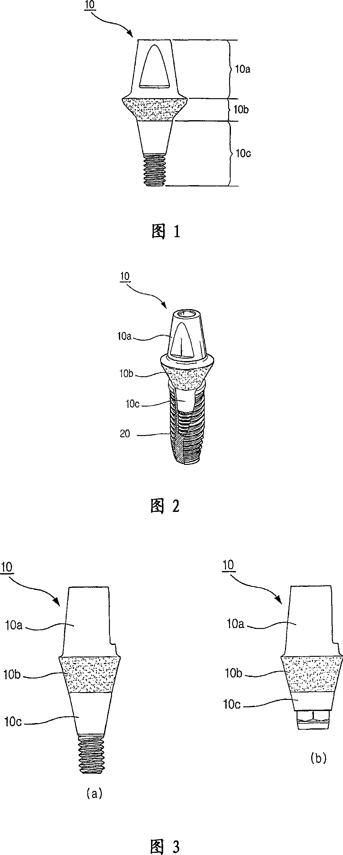
[0018] [18] FIG. 1 is a view illustrating a configuration of an implant abutment 10 according to the present invention; FIG. 2 is a partially cutaway perspective view illustrating a configuration of an implant abutment 10 coupled to a fixture 20 according to the present invention; FIG. 3 is a view illustrating the configuration of an implant abutment 10 according to another embodiment of the present invention.

[0019] [19] The implant abutment 10 according to the present invention is a dental prosthesis for replacing lost or defective teeth. Abutments can be implanted without damaging adjacent teeth and have a long lifespan. As shown in FIGS. 1 to 3 , the implant abutment 10 has a crown connection portion 10 a whose crown (not shown) covers the upper side of the implant abutment 10 . A smooth tissue contact portion 10b is formed at the middle portion of the implant abutment 10, and the smooth tissue contacts with the smooth tissue contact portion 10b. The fixture engaging p...


PUM


Abstract

In an abutment for a dental implant which includes a crown connection part, a smooth tissue contact part and a fixture engaging part, there is provided an improved abutment for a dental implant characterized in that only the smooth tissue contact part is coated. The abutment is made of titanium. The coating process is performed with TiN.

Description

technical field [0001] [01] The present invention relates to an implant abutment, which is composed of a crown connection portion, a smooth tissue contact portion, and a fixture engagement portion, and more particularly, to an implant abutment capable of enhancing The meshing force with the fixture, and the smooth tissue contact part is coated, while the crown connection part and the fixture meshing part are not coated. Background technique [0002] [02] An implant is a dental prosthesis that has been widely used to replace missing or problem teeth. Implants are used without damaging adjacent teeth. It has many advantages in terms of medical effects, and its service life is relatively long. [0003] [03] Before implants are placed, a hole should be drilled in the patient's alveolar bone with a drill. Here, it is very important to drill a hole in the patient's alveolar bone. [0004] [04] The artificial tooth root is called a fixture, which is implanted into the alveolar ...

Claims


Application Information

Patent Timeline
Patent Type & Authority Applications(China)
IPC IPC(8): A61C8/00A61C13/08A61C13/00
CPCA61C8/0069A61C8/0013A61C8/0012A61C8/006A61C8/005A61C8/00
Inventor 郑性闷曹殉道尹球烈金仁浩李泫根
Owner 登腾株式会社
Learn More