Modular switching equipment

A switchgear and modular technology, applied in the direction of electric switches, protection switches, components of protection switches, etc., can solve the problem of not being able to obtain detachable fixation of functional modules, and achieve the effect of simple replaceability

Inactive Publication Date: 2008-06-25
SIEMENS AG
View PDF4 Cites 5 Cited by
  • Summary
  • Abstract
  • Description
  • Claims
  • Application Information

AI Technical Summary

Problems solved by technology

It is impossible to obtain a solution for detachably fixing th

Method used


Image

  • Modular switching equipment
  • Modular switching equipment

Examples


Embodiment Construction

[0018] Like parts and quantities are indicated by like reference symbols in the various figures.

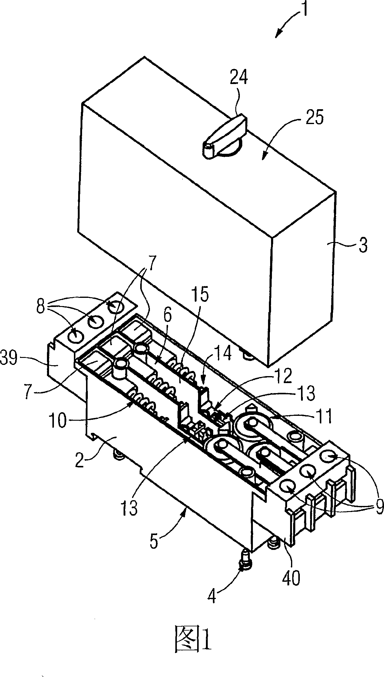
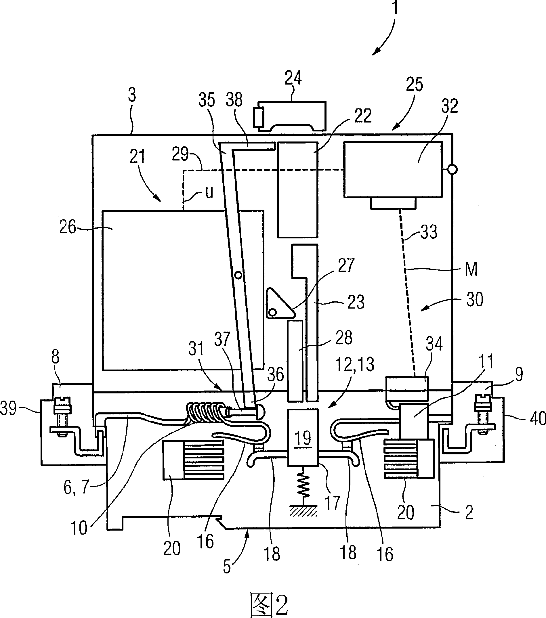
[0019] The switchgear 1 shown in FIG. 1 comprises a switch box 2 and a base module 3 which can be plugged into the switch box. Wherein, the switch box 2 and the basic module 3 can be fixed together by fastening screws 4, and the fastening screws 4 can be operated from the switch box 2 away from the bottom surface 5 of the basic module 3, wherein, when the switch box 2 needs to be replaced, it can be The screw connection is released in a destructive manner, so as to continue to use the basic module 3 after replacing the switch box 2 .

[0020] The switching device 1 is implemented as a three-pole switching device and comprises a main circuit 6 which is divided into three individual lines 7 corresponding to the number of poles. Each single line 7 serves to conduct current between a first connection terminal 8 and a second connection terminal 9 . Inside each individual line 7 of t...


PUM


Abstract

A modular construction for a switchgear (1) is disclosed in order to be able to use a switchgear (1) in a simple manner at least partly during the electrical life thereof. Said switchgear (1) comprises a switching chamber (2), containing a switch unit (12) arranged in a main supply line (6) and a base module (3) detachably mounted on the switch chamber (2) with a mechanical and/or electrically controlled trigger mechanism (21) for operation of the switch unit (12). The main supply line (6) runs exclusively within the switch chamber (2).

Description

technical field [0001] The invention relates to a modular switching device according to the preamble of claim 1 . Background technique [0002] The availability of (low-voltage) switching devices is often limited by the so-called electrical lifetime. The electrical life of the switchgear ends when the contact material on the switchgear contact elements is completely exhausted or when the stationary and moving contacts are welded together. The contact material consumption of the contactor is related to the switching load. The electrical life of the power switch mainly depends on the intensity of the short-circuit current being cut off. [0003] Since the mechanical life of switchgear is generally much longer than its electrical life, the dynamic and static contacts of large-sized contactors can often be replaced individually. Therefore, the remaining components of the switchgear can continue to be used after the electrical life of the switchgear ends. . However, the repla...

Claims


Application Information

Patent Timeline
IPC IPC(8): H01H89/08H01H71/02
CPCH01H89/08H01H71/0228H01H2011/0037
Inventor 罗伯特·阿邓卡克里斯琴·戈盖斯尔约瑟夫·格拉夫巴多·科普曼曼纽拉·利夫特尔马赛厄斯·沃尔兹
Owner SIEMENS AG
Why Eureka
Try Eureka