
Coating liquid supplying device

A technology of a supply device and a coating device, which is applied to a device for coating liquid on a surface, a liquid spray device, a spray device, etc., can solve problems such as easy inflow of air

Active Publication Date: 2010-11-17
CHUGAI RO CO LTD
View PDF6 Cites 0 Cited by
  • Summary
  • Abstract
  • Description
  • Claims
  • Application Information

AI Technical Summary

Problems solved by technology

Furthermore, since the syringe pump is installed on the coating device at a position higher than the mold, there is a problem that air easily flows into the syringe pump.

Method used


Image

  • Coating liquid supplying device
  • Coating liquid supplying device
  • Coating liquid supplying device

Examples


Embodiment Construction

[0025] Embodiments of the present invention will be described below with reference to the drawings.

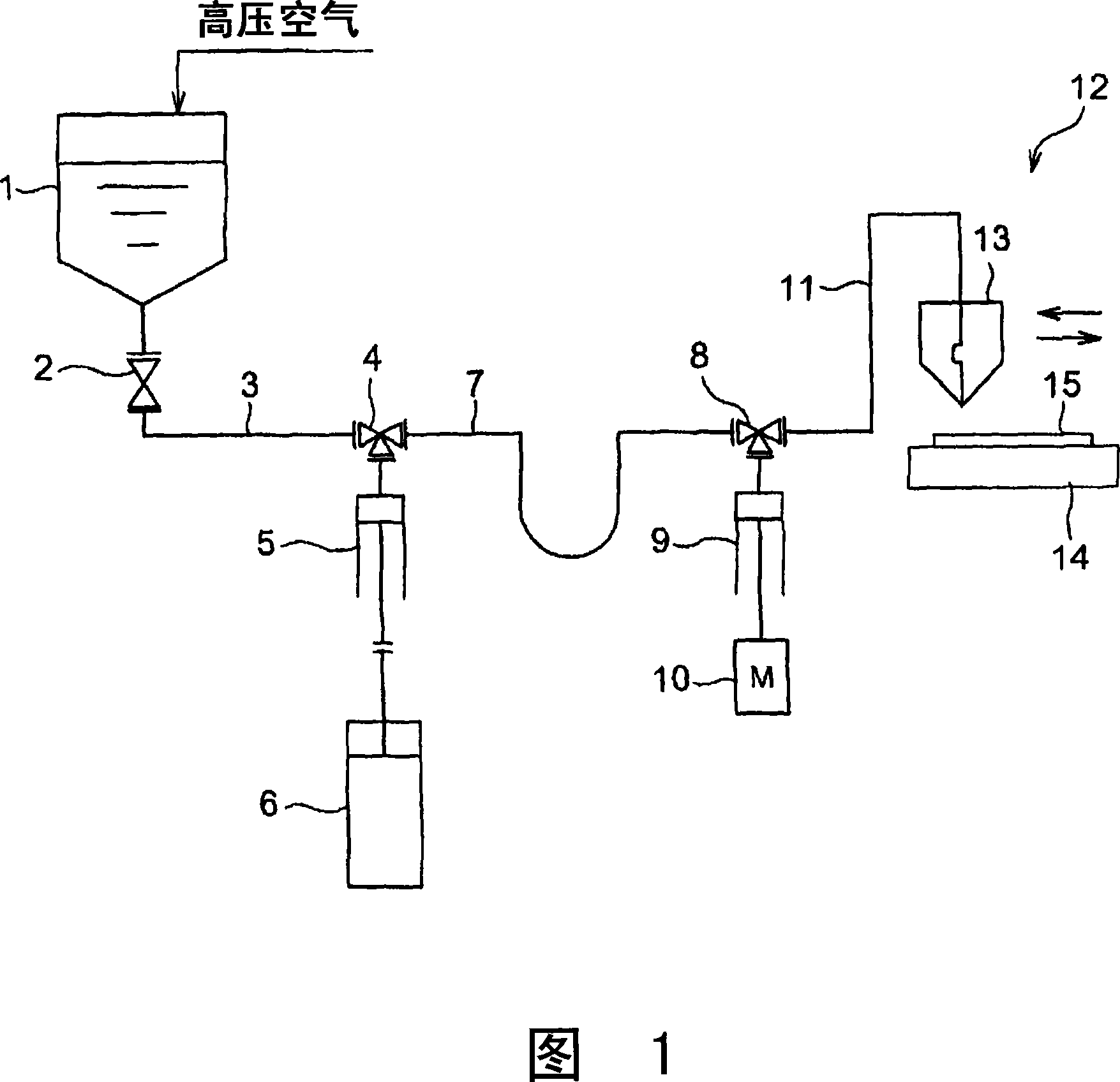
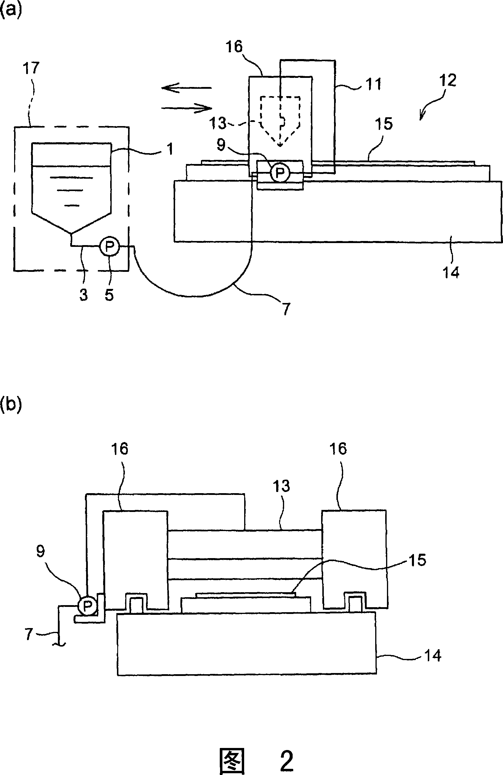
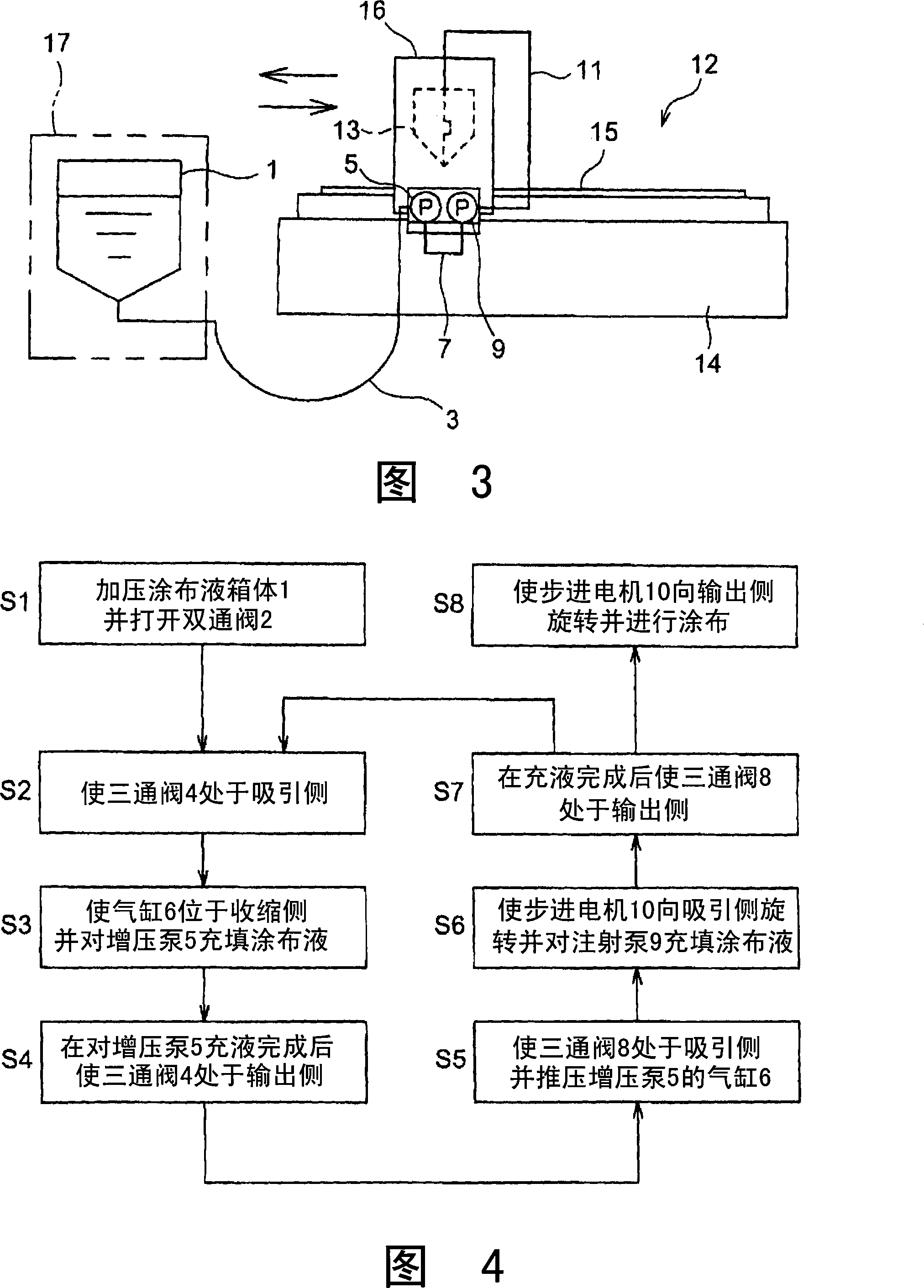
[0026] figure 1 It is a flowchart of the coating liquid supply apparatus of this invention. The coating liquid tank 1 accommodates a necessary amount of coating liquid for coating, and the coating liquid tank 1 can press the coating liquid from below by supplying high-pressure air, but it is not necessary to use high pressure. air, while the coating is hydraulically pumped out by gravity. The coating solution tank 1 is connected to a first suction pipeline 3 through a two-way valve 2 , and the first suction pipeline 3 is connected to a booster pump 5 through a three-way valve 4 . The booster pump 5 is composed of a syringe pump and is driven by an air cylinder 6 . The booster pump 5 is connected to the second suction pipeline 7 through the three-way valve 4 , and the second suction pipeline 7 is connected to the injection pump 9 through the three-way valve 8 . The syringe ...


PUM


Abstract

The present invention provides a coating liquid supply device wherein the suction time of an injecting pump to coating liquid is short and air can not inflow. The coating liquid supply device includes coating liquid case (1) for accepting coating liquid; an injecting pump (9) for sucking coating liquid from the coating liquid case (1) and supplying the coating liquid to a mould (13) of a coating device (12) moving relative to a working table (14) along a prescribed direction; a pressure pump (5) locating between the coating liquid case (1) and the injecting pump (9), sucking and getting off the coating liquid from the coating liquid case (1) to the injecting pump (9) which is installed on a side face of the coating device (12) which is on the square with the moving direction of the mould (13).

Description

technical field [0001] The present invention relates to a coating liquid supply device for supplying a coating liquid to a die of a coating device such as a table coater. Background technique [0002] Conventionally, as a supply device for supplying a coating liquid to a die of a die coater, as shown in Patent Document 1, it includes a coating liquid tank for accommodating the coating liquid, and suction from the coating liquid tank. A syringe pump that supplies the coating liquid to a mold of a coating device that relatively moves in a predetermined direction with respect to a table. The method of installing the syringe pump can be divided into a fixed type in which the syringe pump is fixed at a position separated from the coating device, and a mount type in which the syringe pump is mounted on the coating device and moves together with the mold. [0003] In the fixed type, in order to ensure the moving distance of the coating device, the output pipeline of the coating li...

Claims


Application Information

Patent Timeline
Patent Type & Authority Patents(China)
IPC IPC(8): B05B9/04B05C11/10
CPCB05C5/0225B05C11/10
Inventor 西尾勤松岛克巳梶谷雅一
Owner CHUGAI RO CO LTD
Learn More