Lifting frame device and circular cooler with same

A hanger and sealing device technology, applied in the field of iron and steel smelting, can solve problems such as cumbersome operation and poor safety, and achieve the effects of improving operation safety, facilitating operation, and reducing operating height

Active Publication Date: 2013-04-24
ZHONGYE-CHANGTIAN INT ENG CO LTD
View PDF4 Cites 0 Cited by
  • Summary
  • Abstract
  • Description
  • Claims
  • Application Information

AI Technical Summary

Problems solved by technology

[0010] Obviously, due to the limitations of its own structure, in the actual repair and maintenance work, the above scheme has the defects of too cumbersome operation and poor safety

Method used


Image

  • Lifting frame device and circular cooler with same
  • Lifting frame device and circular cooler with same
  • Lifting frame device and circular cooler with same

Examples


Embodiment Construction

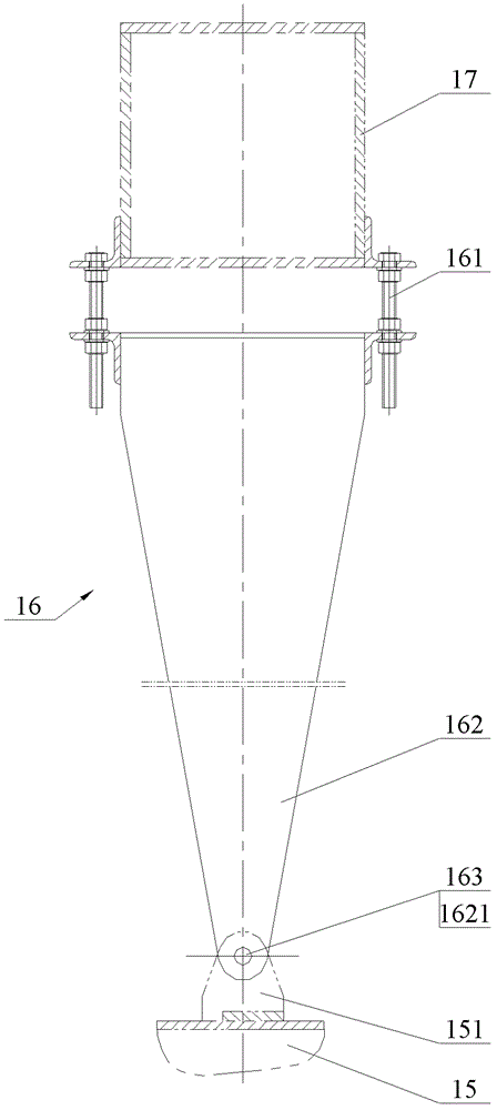
[0040] The core of the present invention is to provide a hanger device for hoisting the door-shaped sealing device on the support beam of the trolley, which can effectively use the screw thread to adjust the overall length to meet the assembly requirements of the door-shaped sealing device. The advantages of operation; at the same time, it provides an effective guarantee for improving operation safety.

[0041] Without loss of generality, this embodiment will be described in detail below in conjunction with the accompanying drawings.

[0042] The orientation words involved in this article, such as upper and lower, are defined based on the use status of the annular cooler. It should be understood that the use of the above orientation words, such as upper and lower, does not limit the scope of protection claimed in this application.

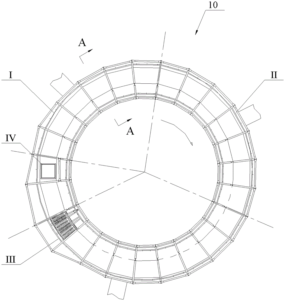
[0043] The annular cooler described in this embodiment is roughly divided into high-temperature zone I, medium-temperature zone II, low-temperatur...


PUM


Abstract

A hanger device (50) and an annular cooler having same, the hanger device (50) comprising a hanger fastener (51) and four connecting pieces (52, 53, 54, 55) disposed in sequence from top to bottom; the upper end of the first connecting piece (52) is hinge-connected to the hanger fastener (51); between the opposing ends of the second connecting piece (53) and the first connecting piece (52) is a first threaded fit; the opposing ends of the third connecting piece (54) and of the second connecting piece (53) are nested together, and between the two opposing ends is allowed a vertical relative displacement with mating lower-stop limiting units (E); between the opposing ends of the fourth connecting piece (55) and the third connecting piece (54) is a second threaded fit, the lower end of the fourth connecting piece (55) being used to hinge-connect to a gate-type sealing device (60); and the sum of the vertical unscrewed lengths of the first threaded fit and the second threaded fit is greater than or equal to a vertical preset distance (L); the minimum vertical relative displacement between the third connecting piece (54) and the second connecting piece (53) enables both the first connecting piece (52) and the fourth connecting piece (55) to rotate around respective hinge points. The hanger device (50) has improved operability for installation and adjustment.

Description

technical field [0001] The invention relates to the field of iron and steel smelting, in particular to a ring cooler and a hanger device for a door-type sealing device thereof. Background technique [0002] Annular coolers are used in iron and steel enterprises to cool sintered high-temperature materials. The annular cooler has a circular shape as a whole, and is divided into a cooling zone and a non-cooling zone along the circumference. During the operation, the ore to be cooled is poured into each ring cooler trolley from the charging station in the non-cooling area, and after entering the cooling area, the ore is cooled by the pressure wind, and then each ring cooler trolley enters the non-cooling machine. The unloading station in the area completes cooling and unloading. [0003] See figure 1 and figure 2 ,in, figure 1 is a schematic diagram of the overall structure of the ring cooler, figure 2 for figure 1 A-A partial sectional view of the annular cooler shown....

Claims


Application Information

Patent Timeline
Patent Type & Authority Patents(China)
IPC IPC(8): F27D15/02
CPCF27D15/02F27D15/0213F27B21/00F27D15/0273
Inventor 高德亮翟鑫
Owner ZHONGYE-CHANGTIAN INT ENG CO LTD
Why Eureka
Try Eureka