
Display device

A display device and a technology for displaying signals, applied in static indicators, nonlinear optics, optics, etc., can solve problems such as slow liquid crystal display speed and image smearing, and achieve the effect of saving costs and adjusting the working cycle

Inactive Publication Date: 2008-07-02
ULTRA CHIP INC
View PDF0 Cites 4 Cited by
  • Summary
  • Abstract
  • Description
  • Claims
  • Application Information

AI Technical Summary

Problems solved by technology

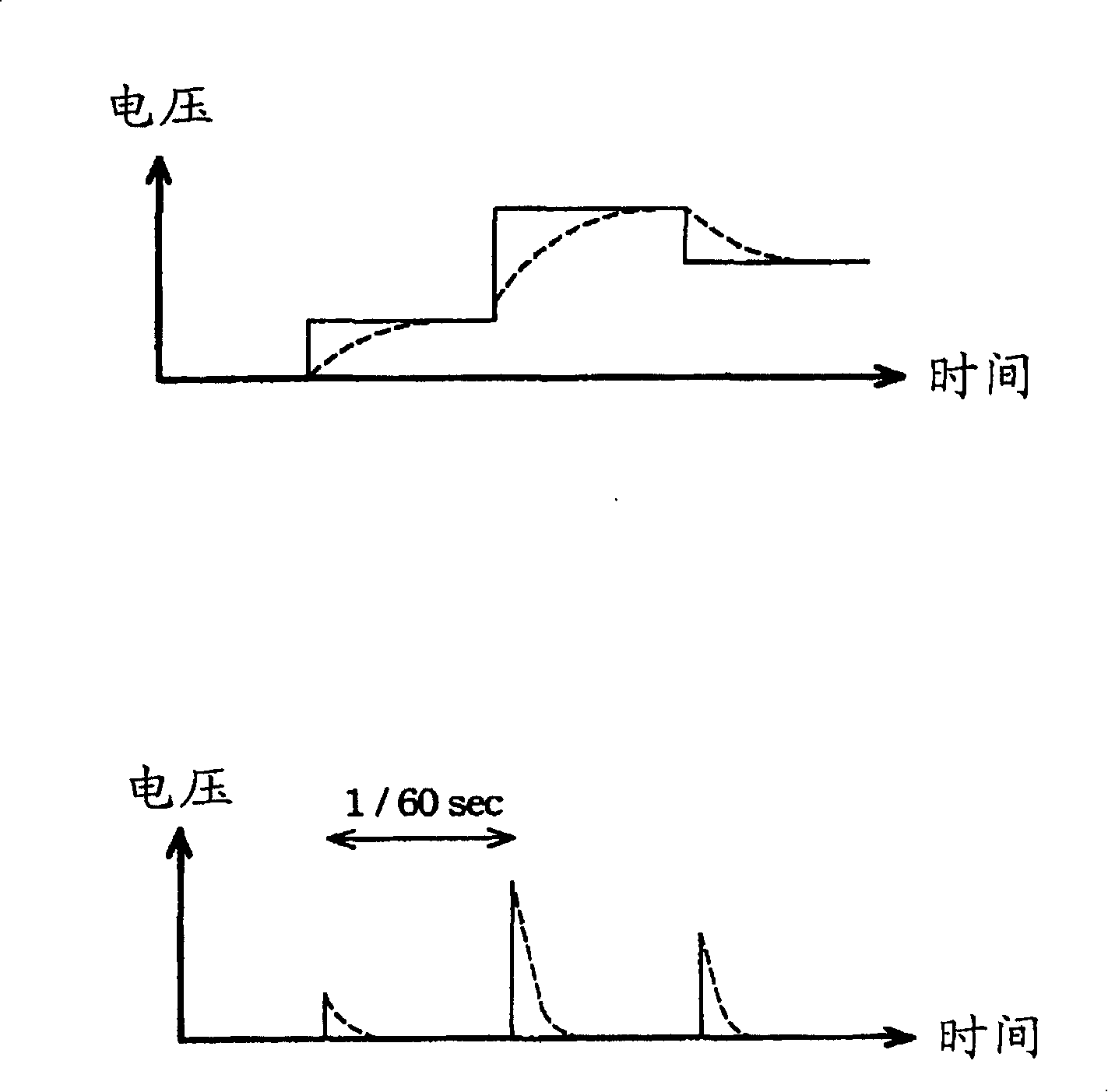
[0006] Based on the above, in the current liquid crystal display, due to the slow speed of the liquid crystal display or the persistence of vision of the user's eyes, the screen will have a smear phenomenon.

Method used


Image

  • Display device
  • Display device
  • Display device

Examples


Embodiment Construction

[0032] The present invention will be described in detail below in conjunction with the accompanying drawings.

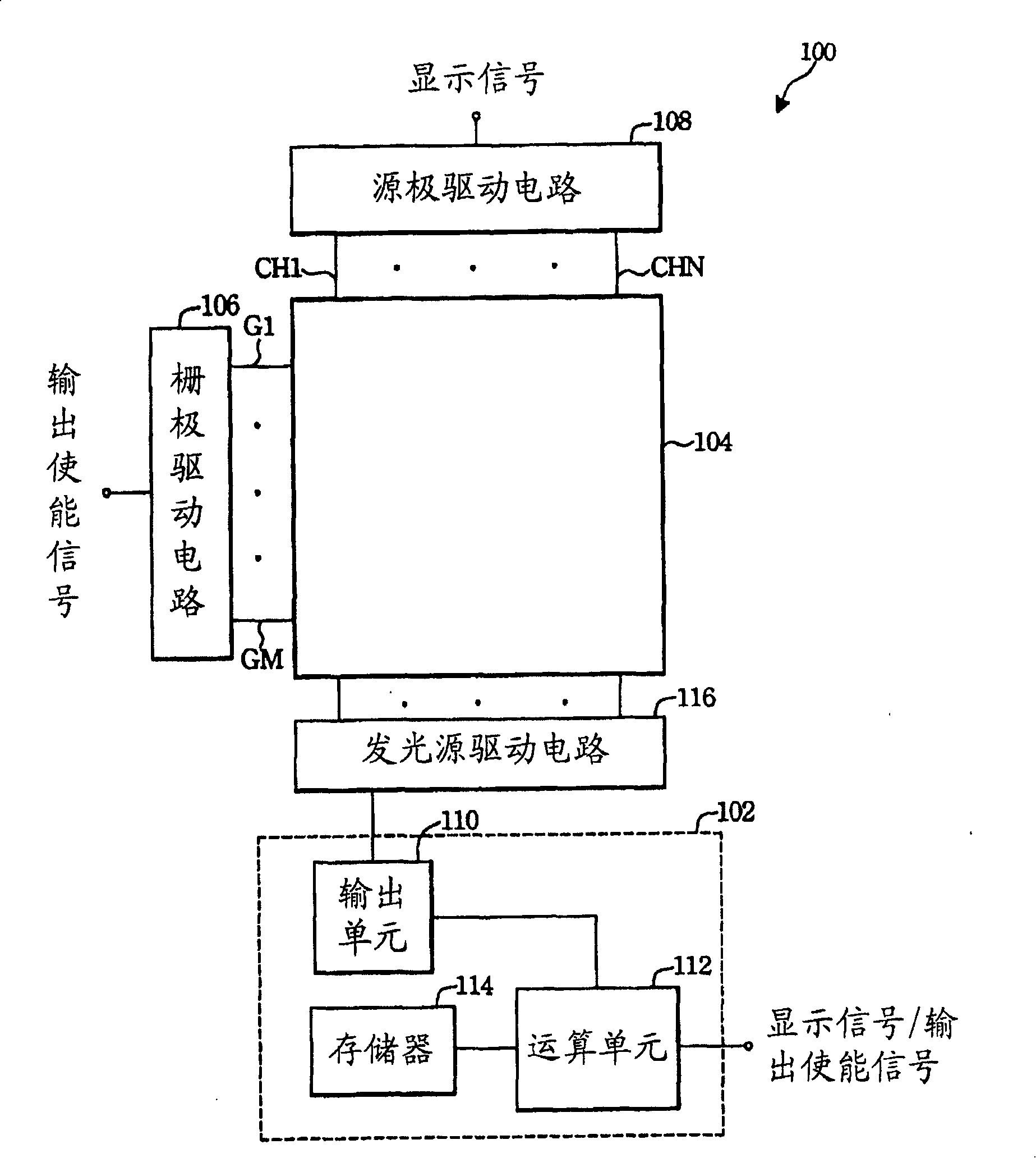
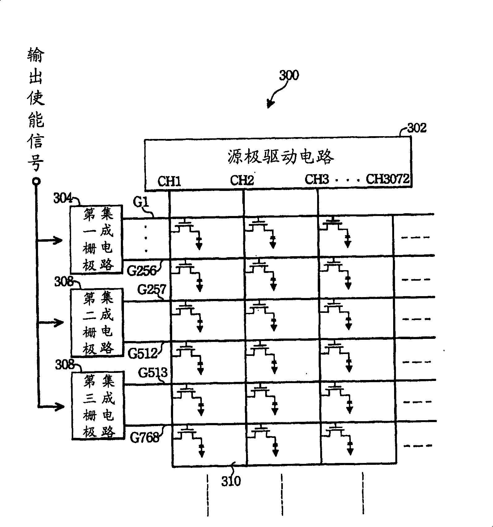
[0033] Please refer to figure 1 , which shows a circuit block diagram of a display device according to a preferred embodiment of the present invention. The display device 100 includes a backlight module driving circuit 102 , a backlight module 104 , a source driving circuit 108 , a gate driving circuit 106 and a light source driving circuit 116 . Wherein, the display area of ​​the display device 100 is composed of a plurality of pixel blocks formed by the gate driving lines G1-GM and the source driving lines CH1-CHN.

[0034] In a preferred embodiment of the present invention, the gate driving circuit 106 receives an output enable signal from, for example, a timing controller (T-CON) to drive the gate driving lines G1˜GM.

[0035] In a preferred embodiment of the present invention, the source driving circuit 108 receives display signals from, for example, the cent...


PUM


Abstract

The invention provides a display device including a backlight module, a driving circuit of the backlight module, and a driving circuit of a light source; the backlight module has at least one backlight unit; the driving circuit of the backlight module contains a memorizer, an arithmetic unit and an output unit, wherein the arithmetic unit receives a display signal and make the black frame insertion operation to the display signal according to a default table of a panel to output an inserted black signal; the output unit receives and selectively outputs an enabling signal or an unable signal according to the inserted black signal; the driving circuit of the light source outputs a brightens control signal to into the backlight unit according to the enabling signal and the unable signal. The invention directly control an LED to be enable or to be unable according to the brightness of the display signal of the display device, which can not only save cost of the display device, but can adjust the working period of the display device as well.

Description

technical field [0001] The present invention relates to a display, in particular to a display device that utilizes a backlight module driving circuit to quickly switch light-emitting diodes in a backlight unit. Background technique [0002] Early thin film transistor liquid crystal display (Thin Film Transistor Liquid Crystal Display, referred to as TFT-LCD) is mainly applied in the screen of a notebook computer (notebook, referred to as NB) or a personal computer, so most of its image signals are static images. However, in recent years, due to the research and development of various liquid crystal display manufacturers, liquid crystal display technology has gradually been applied to large-size TFT-LCDs, and image signals have changed from static to dynamic image signals. However, the current TFT-LCD adopts a hold-type display, that is, the pixel keeps displaying the current data before the next data is written into the pixel. Therefore, such a hold mode (the relationship b...

Claims


Application Information

Patent Timeline
Patent Type & Authority Applications(China)
IPC IPC(8): G02F1/133G09G3/36G09G3/34G09G3/20G02F1/167G02F1/15
Inventor 吴泰峰
Owner ULTRA CHIP INC
Learn More