End milling cutter

A technology of end mills and tool holders, which is applied in the direction of milling cutters, milling machine equipment, manufacturing tools, etc., and can solve problems such as difficult and expensive manufacturing

Inactive Publication Date: 2008-07-02
SANDVIK INTELLECTUAL PROPERTY AB
View PDF0 Cites 7 Cited by
  • Summary
  • Abstract
  • Description
  • Claims
  • Application Information

AI Technical Summary

Problems solved by technology

However, with the required level of precision known from other cutting tools with fixed combined cutting parts, cutting parts of this type with complex coupling elements and corresponding counter parts on the tool shank complex and expensive to manufacture, and difficult to manufacture

Method used


Image

  • End milling cutter
  • End milling cutter
  • End milling cutter

Examples


Embodiment Construction

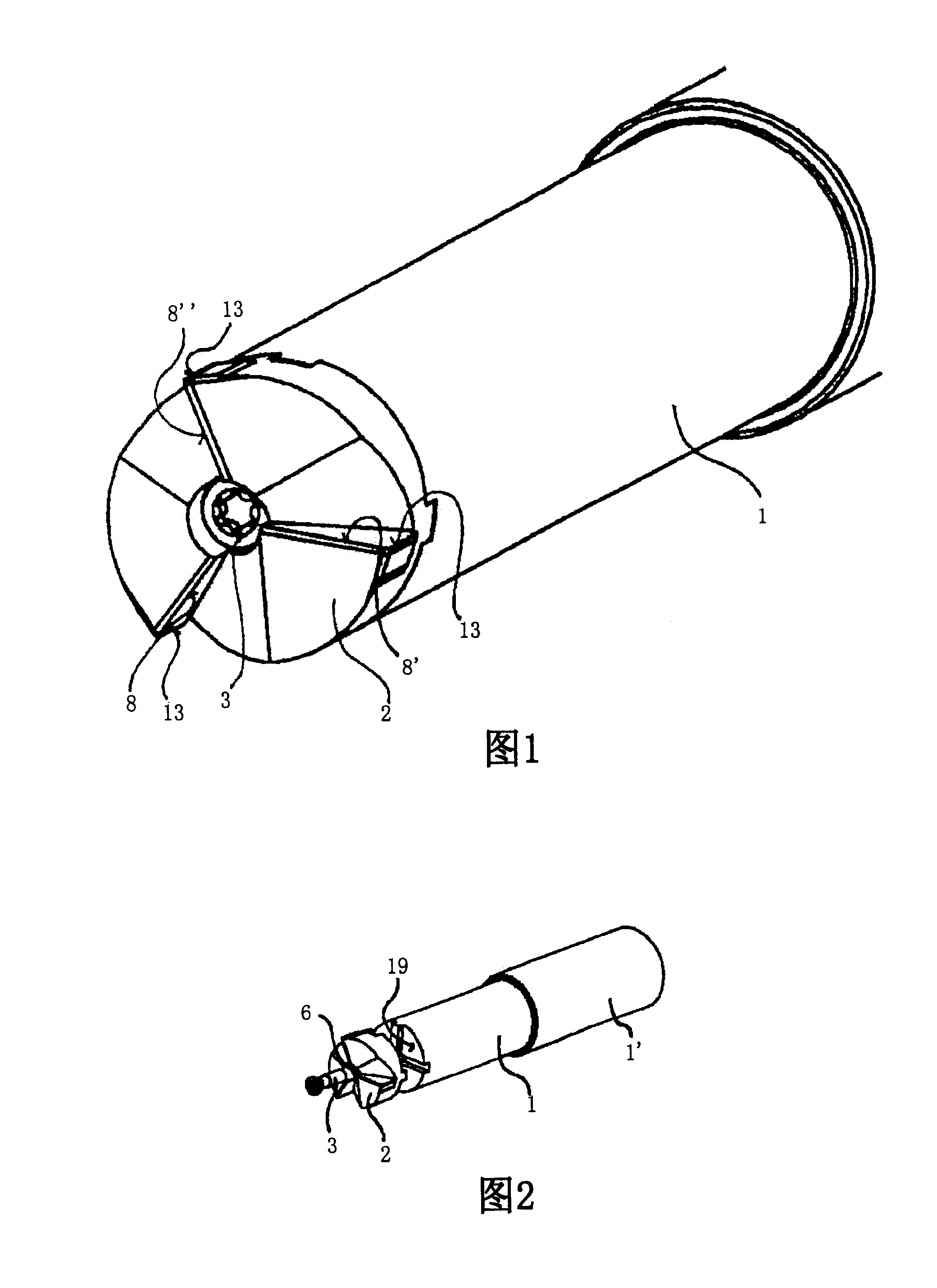
[0038] Referring to FIG. 1 , there is shown an end mill comprising a shank 1 and a cutting portion 2 which is integral and releasably secured to the end of the shank by a screw 3 . Figure 2 shows an exploded perspective view of the same end mill so that the three main components, namely the shank 1, the cutting part 2 and the screw 3, can be seen as separate parts which can be separated from each other and connected as a whole to form a stand A milling cutter which, in addition to the peripheral cutting edge 13, also has end cutting edges 8, 8', 8".

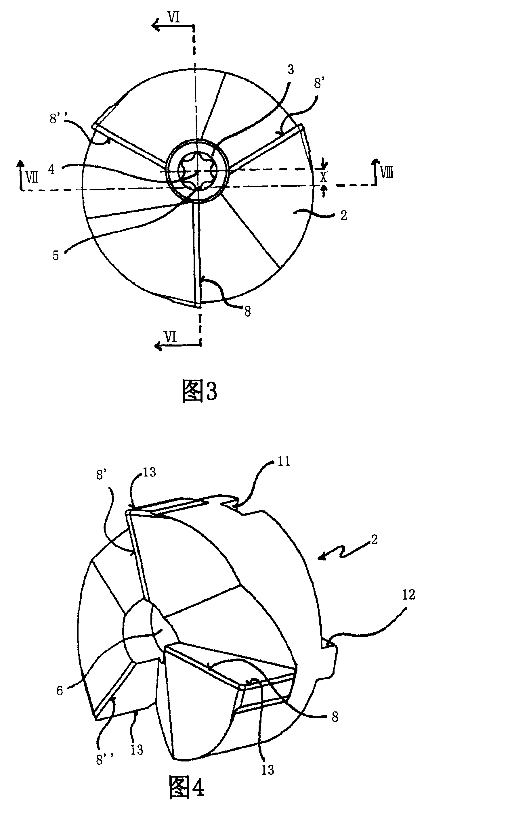
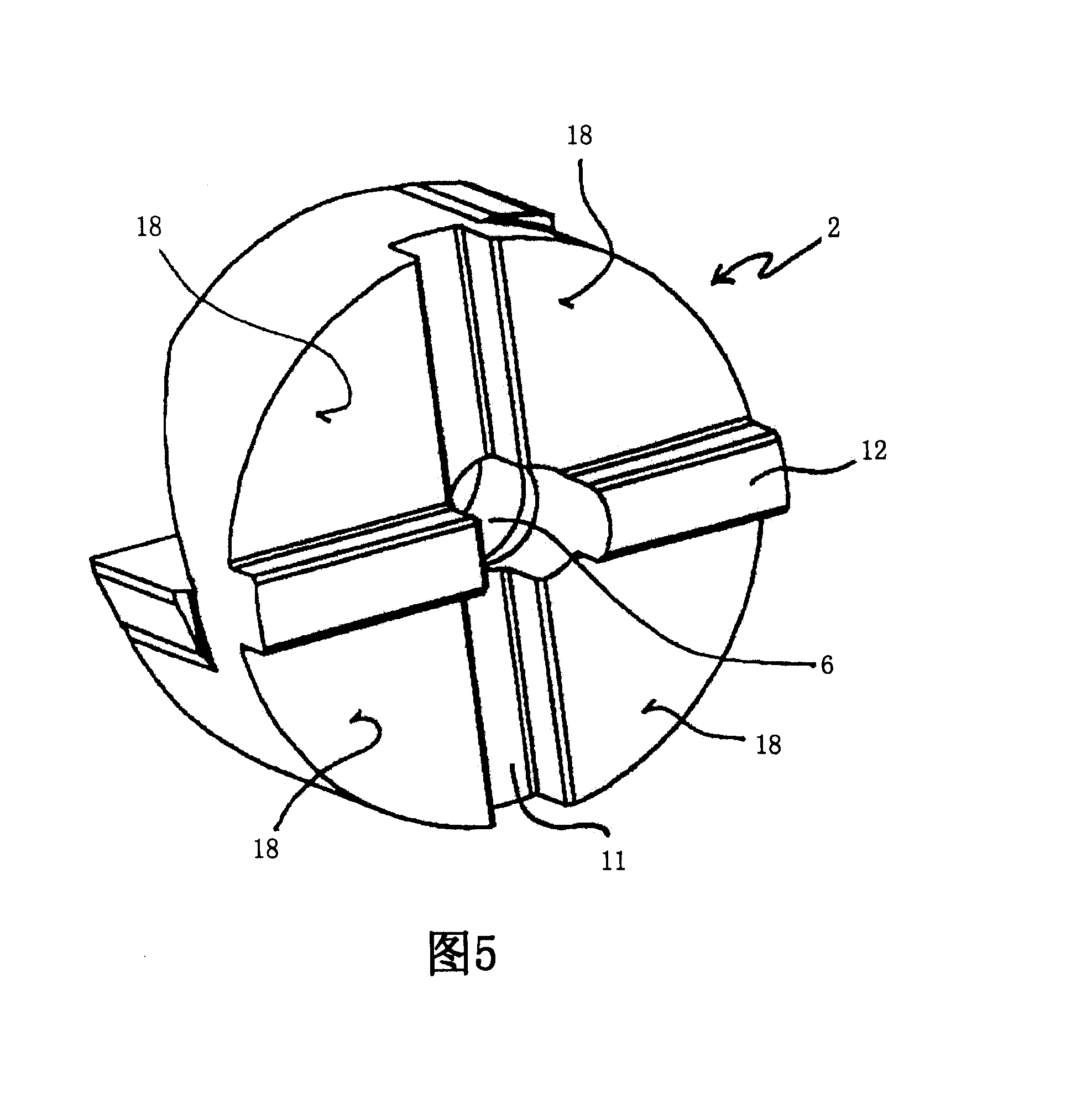
[0039] Further details will be apparent by reference to the enlarged views of FIGS. 3 to 8 .

[0040] The end view of the milling cutter shown in FIG. 3 mainly shows the end cutting part 2 and the fixing screw 3, which in this case has a so-called "Torx" drive, that is to say the fixing screw 3 has an opening, which adopts In the form of a hexagonal star with a rounded tip and a transition, a drive wrench of corresponding constr...


PUM


Abstract

The present invention relates to an end milling cutter with a shank (l) and a cutting part (2), which consists of a single piece and is detachably secured to the end face of the shank (1) by means of a screw (3). The axis (4) of the screw (3) extends in a direction substantially parallel with the axis (5) of the shank (1) and, via a bore (6) that runs through the cutting part (2), into a threadedbore in the end face of the shank (1). The aim of the invention is to devise an end milling cutter with the aforementioned features, which end milling cutter is configured as a face milling cutter and, in consequence, allows at least a certain degree of axial feed motion whilst at the same time allowing the blades to be accurately positioned relative to the axis of the milling cutter and the milling cutter to be more simply produced than other comparable milling cutters with an interchangeable cutting part. To achieve this aim, according to the invention the axis (4) of the screw (3) is radially offset relative to the axis of the shank (1) and at least one blade (8) on the end face of the cutting part (2) on the side facing away from the offset reaches almost to the borehole that extends through the cutting part (2).

Description

technical field [0001] The present invention relates to an end mill comprising a shank and a cutting portion which is integral and releasably secured to the end of the shank by a screw, wherein the axis of the screw is substantially parallel to the shank and through a bore into a threaded bore provided in the end of the shank, which bore extends through the cutting portion. Background technique [0002] Corresponding end mills are already known in the art and commercially available. Among the holders of end mills, those known end mills have a central axis hole into which a set screw fits and is also engaged centrally by the cutting portion. In this respect, it is also known that instead of the hole a cutting part has an integrated central threaded bolt by which the cutting part is secured in a threaded hole in the tool holder. Furthermore, drill bits are known which have an integral interchangeable cutting portion at their tip. In order to fix such a cutting part in place...

Claims


Application Information

Patent Timeline
Patent Type & Authority Applications(China)
IPC IPC(8): B23C5/10
CPCB23C2210/03B23C2210/02B23C5/10B23C5/02
Inventor 京特·维尔梅斯特
Owner SANDVIK INTELLECTUAL PROPERTY AB
Why Eureka
Try Eureka