Cooling box and its control method

A cooling box and box body technology, applied in refrigerators, refrigeration components, refrigeration and liquefaction, etc., can solve problems such as inability to guarantee temperature, and achieve the effects of convenient installation and maintenance, reliable operation, and reduced heat load

Inactive Publication Date: 2008-07-09
董练红
View PDF0 Cites 18 Cited by
  • Summary
  • Abstract
  • Description
  • Claims
  • Application Information

AI Technical Summary

Problems solved by technology

However, if the ambient temperature or room temperature is high, relying on exhaust fans for ventilation does not guarantee that the temperature is within the operating range

Method used


Image

  • Cooling box and its control method

Examples


Embodiment 1

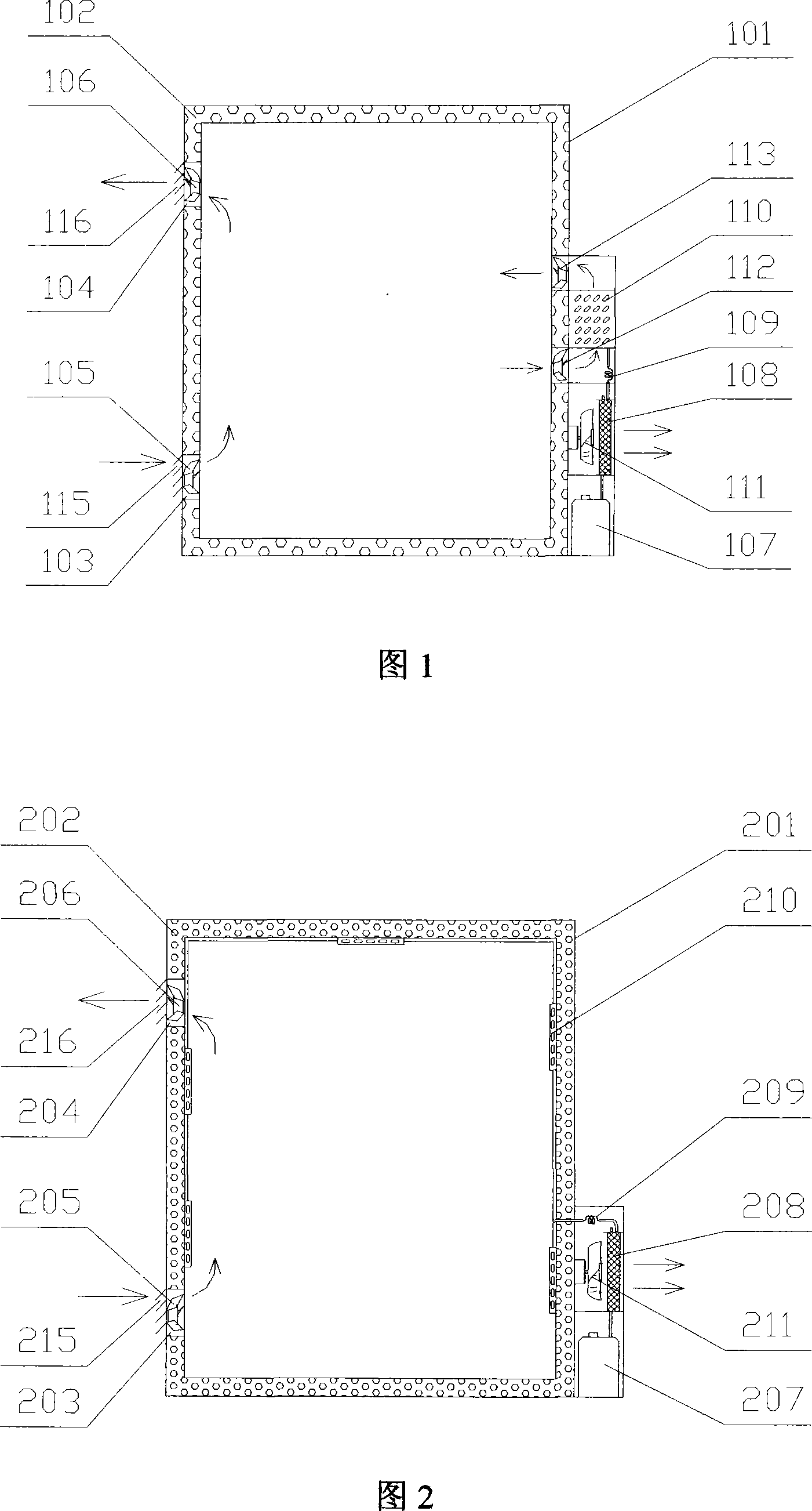
[0025] This embodiment describes an external air duct type cooling box, as shown in Figure 1, including a box body, a ventilation system and a refrigeration system.

[0026] The box body (101) is an incubator with a thermal insulation layer (102). The thermal insulation layer (102) uses polyurethane foam material. When the size of the box is small, the thermal insulation layer can be foamed as a whole; when the size of the box is large, the insulation board can be cut according to the structural size and installed on the surface of the box. There is a door seal between the door body and the box body of the incubator, which can reduce heat leakage from the gap between the door body and the box body after the incubator is closed.

[0027] The box body (101) is provided with an air inlet (103) and an air outlet (104) communicating with the outside. In order to facilitate heat dissipation, the air inlet (103) is arranged at the lower part of the box body, and the air outlet is a...

Embodiment 2

[0041] This embodiment describes a built-in direct cooling cooling box, as shown in Figure 2, including a box body, a ventilation system and a refrigeration system.

[0042] The box body (201) is an incubator with a thermal insulation layer (202). The thermal insulation layer (102) uses polyurethane foam material. The box body (201) is provided with an air inlet (203) and an air outlet (204) communicating with the outside. In order to facilitate heat dissipation, the air inlet (203) is arranged at the lower part of the box body, and the air outlet is arranged at the upper part (204) of the box body.

[0043] The ventilation system includes a ventilation fan and a ventilation fan motor. In this embodiment, an air inlet fan (205) and an air outlet fan (206) are respectively provided at the air inlet (203) and the air outlet (204) to realize air circulation. In order to reduce the heat dissipation of the cooling box during cooling operation, the air inlet and outlet are provid...


PUM


Abstract

The invention provides a cooling tank which comprises a tank body, a ventilation system and a refrigeration system. The box body is an incubator with heat-insulating layer and provided with at least one air inlet and at least one air outlet, where the air inlet and the air outlet are communicated with the external environment and provided with openable / closable air inlet and outlet doors respectively. The ventilation system comprises a ventilating fan and a ventilating fan motor. The refrigeration system is the device which is powered by electric energy or solar energy and can supply cold energy to the interior of a refrigeration air-conditioning cabinet and discharge heat energy out of the refrigeration air-conditioning cabinet. The inventive cooling tank runs in ventilation mode, refrigeration mode or a combination thereof; provides ventilation and cooling effect under the condition of low environmental temperature; and can cool the tank body and equipment by electrical refrigeration under the condition of high environmental temperature. Compared with prior art, the invention has the advantages of good economic efficiency, low energy consumption, reliable operation, and convenient installation and maintenance.

Description

technical field [0001] The invention relates to a temperature control device, in particular to a cooling and temperature-regulating box operating in dual modes of ventilation and cooling, and also relates to a method for controlling the energy-saving operation of the cooling box. Background technique [0002] A class of instruments and equipment, such as electronic instruments, batteries, etc., whose working conditions require the environment to be kept at an appropriate temperature. When the temperature is too high, it cannot work normally or the failure rate increases and the service life decreases. Usually, the requirement for the ambient temperature is a wide temperature range, as long as the temperature does not exceed the upper and lower limits, precise temperature control is not required. In order to control the ambient temperature within the working range, the common method is to place the instrument and equipment indoors, and install air-conditioning and refrigerati...

Claims


Application Information

Patent Timeline
Patent Type & Authority Applications(China)
IPC IPC(8): F25B1/00F25B21/02F25B49/00
Inventor 董练红
Owner 董练红
Why Eureka
Try Eureka