A three frequency band filter based on parallel coupled line structure

A technology of parallel coupling lines and parallel coupling, which is applied in the direction of waveguide devices, resonators, electrical components, etc., can solve the problem of not being able to provide coupling coefficients, and achieve the effect of simple and fast design process and reduced dependence

Active Publication Date: 2008-07-09
SOUTHEAST UNIV
View PDF0 Cites 2 Cited by
  • Summary
  • Abstract
  • Description
  • Claims
  • Application Information

AI Technical Summary

Problems solved by technology

Ordinary uniform symmetrical parallel coupled lines cannot provide these coupling coefficients

Method used


Image

  • A three frequency band filter based on parallel coupled line structure
  • A three frequency band filter based on parallel coupled line structure

Examples


Embodiment Construction

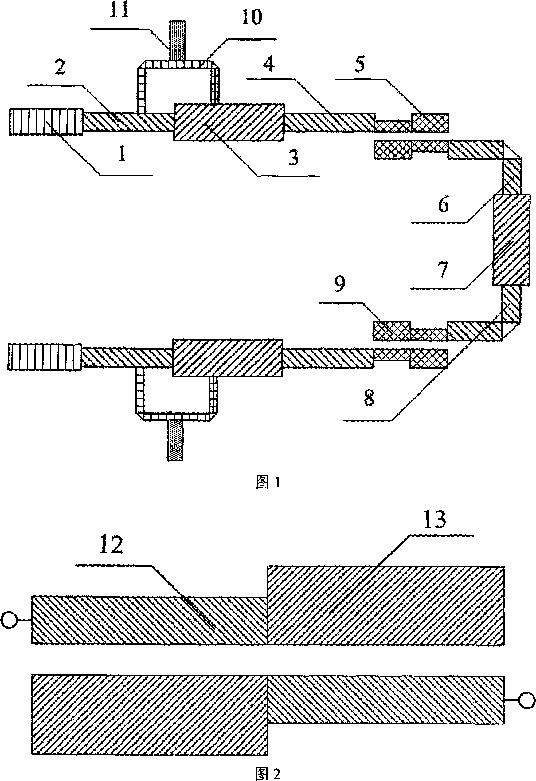
[0016] The three-band filter with controllable bandwidth and adjustable center frequency of the present invention includes the first transmission line 1, the second transmission line 2, the third transmission line 3, and the fourth transmission line 4 of the input and output stage resonator, and the connection between the input and output The first parallel coupling structure 5 composed of asymmetric parallel coupling lines between the resonator and the intermediate resonator, the sixth transmission line 6, the seventh transmission line 7 and the eighth transmission line 8 of the intermediate resonator, and the intermediate resonator The second parallel coupling structure 9 on one side is connected to the contact coupling structure 10 on the second transmission line 2 and the third transmission line 3 of the input-output stage resonator, and an output port 11 is provided on the contact coupling structure 10 . The first parallel coupling structure 5 and the second parallel coupl...


PUM


Abstract

A tri-band filter which is based on a parallel coupling line structure relates to a tri-band filter with controllable bandwidth and adjustable center frequency. An input-output stage resonator is composed of a first transmission line (1), a second transmission line (2), a third transmission line (3) and a fourth transmission line (4), which are connected in series, a first parallel coupling structure (5) is connected with the fourth transmission line (4); a middle stage resonator is composed of a sixth transmission line (6), a seventh transmission line (7) and an eighth transmission line (8) in serial, a second parallel coupling structure (9) is connected with the sixth transmission line (6) and the eighth transmission line (8) and is symmetrical with the first parallel coupling structure (5); a contact coupling structure (10) is connected on the second transmission line (2) and the third transmission line (3) of the input-output stage resonator, and an input-output port (11) is arranged on the contact coupling structure (10). The invention can work in the tri-band filter, the design is simple, the processing is convenient and the cost is low.

Description

technical field [0001] The invention relates to a band-pass filter, in particular to a three-band filter with controllable bandwidth and adjustable center frequency. Background technique [0002] The current market demand for multi-mode multi-band communication systems has created a need for multi-band filters. The previous coupled line filter only focused on the design of the first resonant frequency of the resonator. To achieve multi-band, multiple filters need to be designed separately, which is wasteful in terms of cost and space occupation. [0003] In order for multiple frequency bands to share the same resonator, it is necessary to use the higher resonant frequency of the resonator. Traditional uniform impedance resonators only work at the first resonant frequency f 0 , its higher resonance frequency is fixed at 2f 0 , 3f 0 …superior. In 1997, Professor M.Makimoto and Professor S.Yamashita comprehensively reported the step impedance resonator (three-stage) in the...

Claims


Application Information

Patent Timeline
Patent Type & Authority Applications(China)
IPC IPC(8): H01P1/212H01P7/00
Inventor 崔铁军赵晖程强
Owner SOUTHEAST UNIV
Why Eureka
Try Eureka