Reactor and step-up circuit

A technology of reactors and circuits, applied in circuits, inductors, variable inductors, etc., can solve problems such as increased ripple current

Pending Publication Date: 2019-07-26
TOKIN CORP
View PDF0 Cites 0 Cited by
  • Summary
  • Abstract
  • Description
  • Claims
  • Application Information

AI Technical Summary

Problems solved by technology

In addition, it is also known that when the duty cycle is set to a value far from 0.5 in this case, the ripple current increases significantly as its coupling coefficient increases

Method used


Image

  • Reactor and step-up circuit
  • Reactor and step-up circuit
  • Reactor and step-up circuit

Examples


no. 1 example

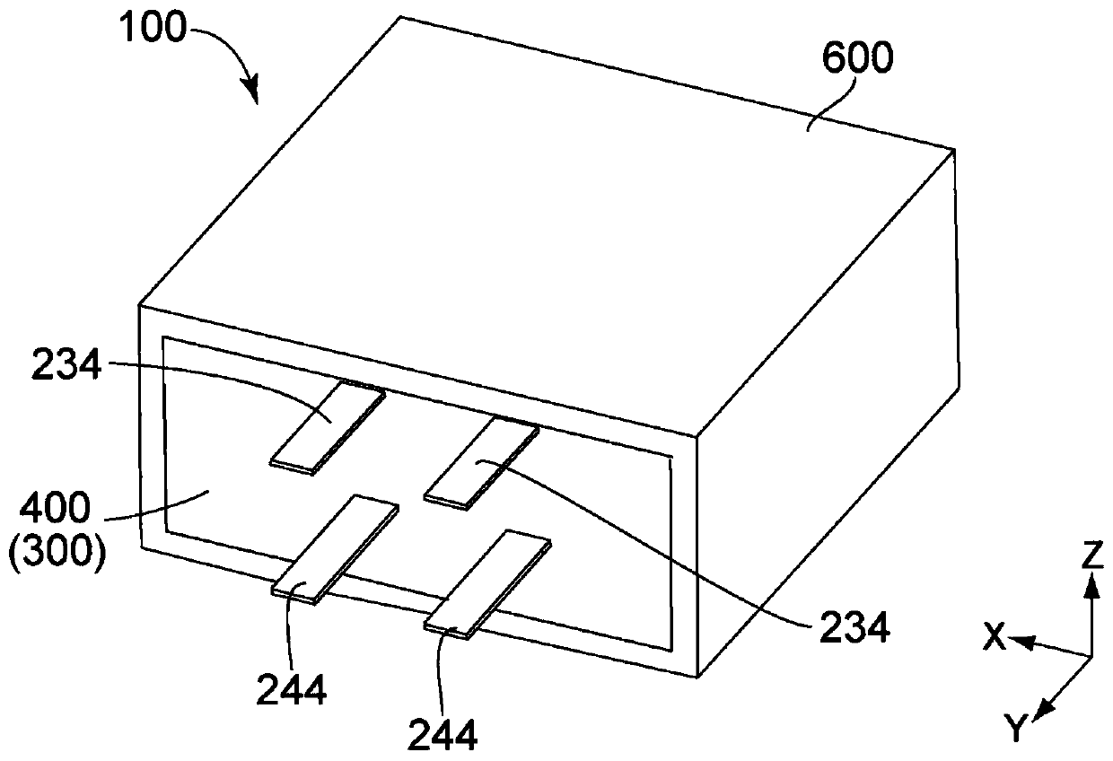
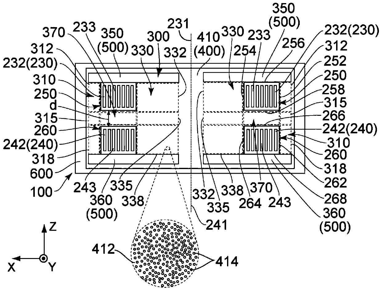
[0023] Such as figure 2 As shown in , the reactor 100 according to the first embodiment of the present invention includes a first coil 230 , a second coil 240 , a core 300 and a case 600 . Each of the first coil 230 and the second coil 240 is embedded in the core 300 .

[0024] see figure 1 and figure 2 , the first coil 230 of this embodiment includes a first coil body 232 and two first end portions 234 . The first coil main body 232 has a first winding axis 231 extending in the up-down direction. The two first end portions 234 respectively extend from opposite ends of the first coil body 232 . In this embodiment, the up and down direction is the Z direction. Specifically, it is assumed that upward is the positive Z direction and downward is the negative Z direction. The first coil main body 232 of this embodiment is formed by level-winding a flat wire 233 . Although the first coil 230 of the present embodiment is a single-layer coil, the present invention is not lim...

no. 2 example

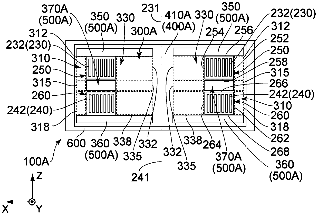
[0059] Such as image 3 As shown in , in addition to the core 300A, the reactor 100A according to the second embodiment of the present invention has the same figure 1 and figure 2 Each of the reactors 100 shown in the foregoing first embodiment has the same structure. therefore, image 3 Components of the reactor 100A shown in , which are the same as those of the reactor 100 of the first embodiment, are denoted by the same reference numerals as those of the reactor 100 of the first embodiment. Regarding directions and orientations in this embodiment, the same expressions as those of the first embodiment will be used hereinafter.

[0060] see image 3 , The core 300A of this embodiment is made of a first member 400A and a second member 500A. The second member 500A of this embodiment is a powder core. The first member 400A of this embodiment is a core made of a composite magnet 410A including hardened binder 412 and magnetic particles 414 . Magnetic particles 414 are di...

no. 3 example

[0068] Such as Figure 4 As shown in , in addition to the core 300B, the reactor 100B according to the third embodiment of the present invention has the same figure 1 and figure 2 Each of the reactors 100 shown in the foregoing first embodiment has the same structure. therefore, Figure 4 Components of the reactor 100B shown in , which are the same as those of the reactor 100 of the first embodiment, are denoted by the same reference numerals as those of the reactor 100 of the first embodiment. Regarding directions and orientations in this embodiment, the same expressions as those of the first embodiment will be used hereinafter.

[0069] see Figure 4 , The core 300B of this embodiment is made of a first member 400B and a second member 500B. The second member 500B of this embodiment is a powder core. The first member 400B of the present embodiment is a core made of a composite magnet 410B including hardened binder 412 and magnetic particles 414 . Magnetic particles 4...


PUM


Abstract

A reactor comprises a first coil, a second coil and a core. Each of the first coil and the second coil is embedded in the core. The core has an outer core part, an inner core part, an upper core part,a lower core part and a middle core part. The upper core part is positioned above an upper end of a cross-section of the first coil in an up-down direction. The lower core part is positioned below alower end of a cross-section of a second coil in the up-down direction. The core is made of a first member and a second member. The second member has a relative permeability which is greater than a relative permeability of the first member. Each of the upper core part and the lower core part is made of the second member.

Description

technical field [0001] The present invention relates to a reactor including two coils and a core, and a booster circuit including the reactor. Background technique [0002] Because an interleaved boost circuit can handle a large current, an interleaved boost circuit using a reactor is required. For example, such an interleaved booster circuit using a reactor is disclosed in Patent Document 1 (JPA H10-127049). For example, a reactor used in such an interleaved booster circuit is disclosed in Patent Document 2 (JPA 2017-168587). refer to Figure 10 , the reactor 800 of Patent Document 2 has two coils 810 , a core 850 and an intermediate cover portion 880 . The core 850 is a casting core formed by mixing soft magnetic alloy powder and resin, and then pouring the mixture into a predetermined mold. Each of the two coils 810 is embedded in a core 850 . The middle cover portion 880 is made of resin and has an annular flat plate. The middle cover part 880 is held between the tw...

Claims


Application Information

Patent Timeline
Patent Type & Authority Applications(China)
IPC IPC(8): H01F27/24H01F27/255H01F27/28H01F27/30H01F29/12H02M1/00
CPCH01F29/12H01F27/24H01F27/255H01F27/306H01F27/2847H02M1/00G05F3/22H01F37/00H01F27/2871H01F17/04H02M3/1584H01F27/022H01F3/14H01F2003/106H02M3/1586H01F27/2823H01F27/02
Inventor 阿部有希山家孝志近藤将宽远藤卓哉赤木启祐
Owner TOKIN CORP
Why Eureka
Try Eureka