
A device and method for generating an optical signal

An optical signal and signal technology, applied in the field of communication, can solve the problem of high cost, and achieve the effect of reducing the complexity of the device, easy implementation and cost reduction

Active Publication Date: 2020-08-14
HUAWEI TECH CO LTD
View PDF6 Cites 0 Cited by
  • Summary
  • Abstract
  • Description
  • Claims
  • Application Information

AI Technical Summary

Problems solved by technology

This solution can be very expensive, especially when transmitting signals at high rates

Method used


Image

  • A device and method for generating an optical signal
  • A device and method for generating an optical signal
  • A device and method for generating an optical signal

Examples


Embodiment Construction

[0042] The technical solutions in the embodiments of the present application will be described below with reference to the accompanying drawings.

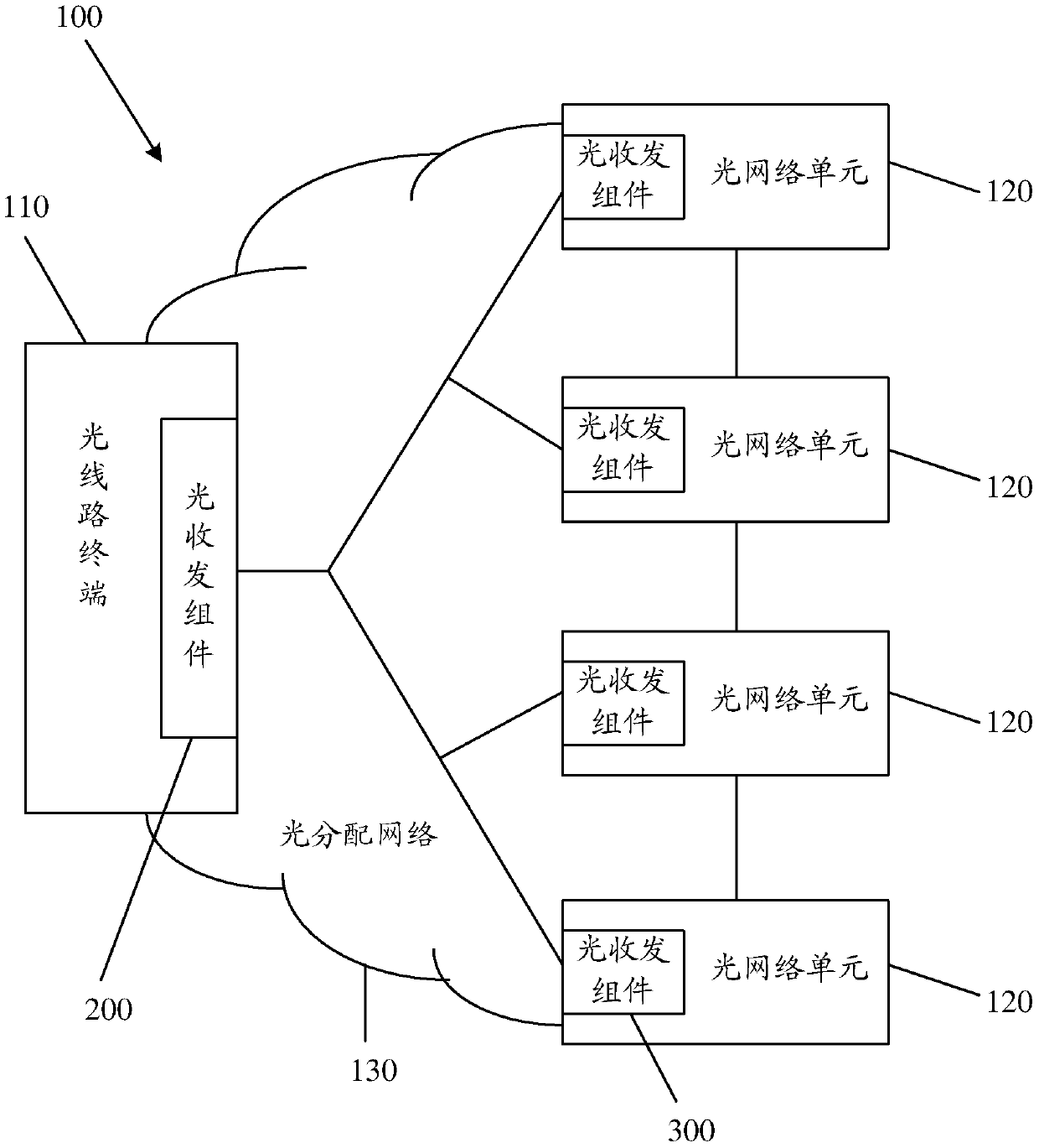
[0043] figure 1 A schematic diagram of a network architecture applied in the embodiment of the present application is shown, and the schematic diagram is a schematic diagram of a network architecture of a PON system to which the apparatus for generating an optical signal provided in the present application can be applied. The PON system 100 includes at least one optical line terminal (optical line terminal, referred to as "OLT") 110, a plurality of optical network units (Optical Network Unit, referred to as "ONU") 120 and an optical distribution network (Optical Distribution Network, referred to as "ODN") ”)130. The OLT 110 is connected to the plurality of ONUs 120 through the ODN 130 in a point-to-multipoint manner. Between the optical line terminal 110 and the optical network unit 120, a time division multiplexing (Time Divisio...


PUM


Abstract

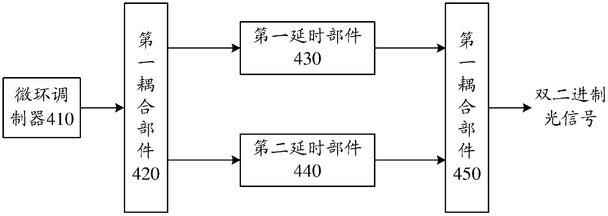
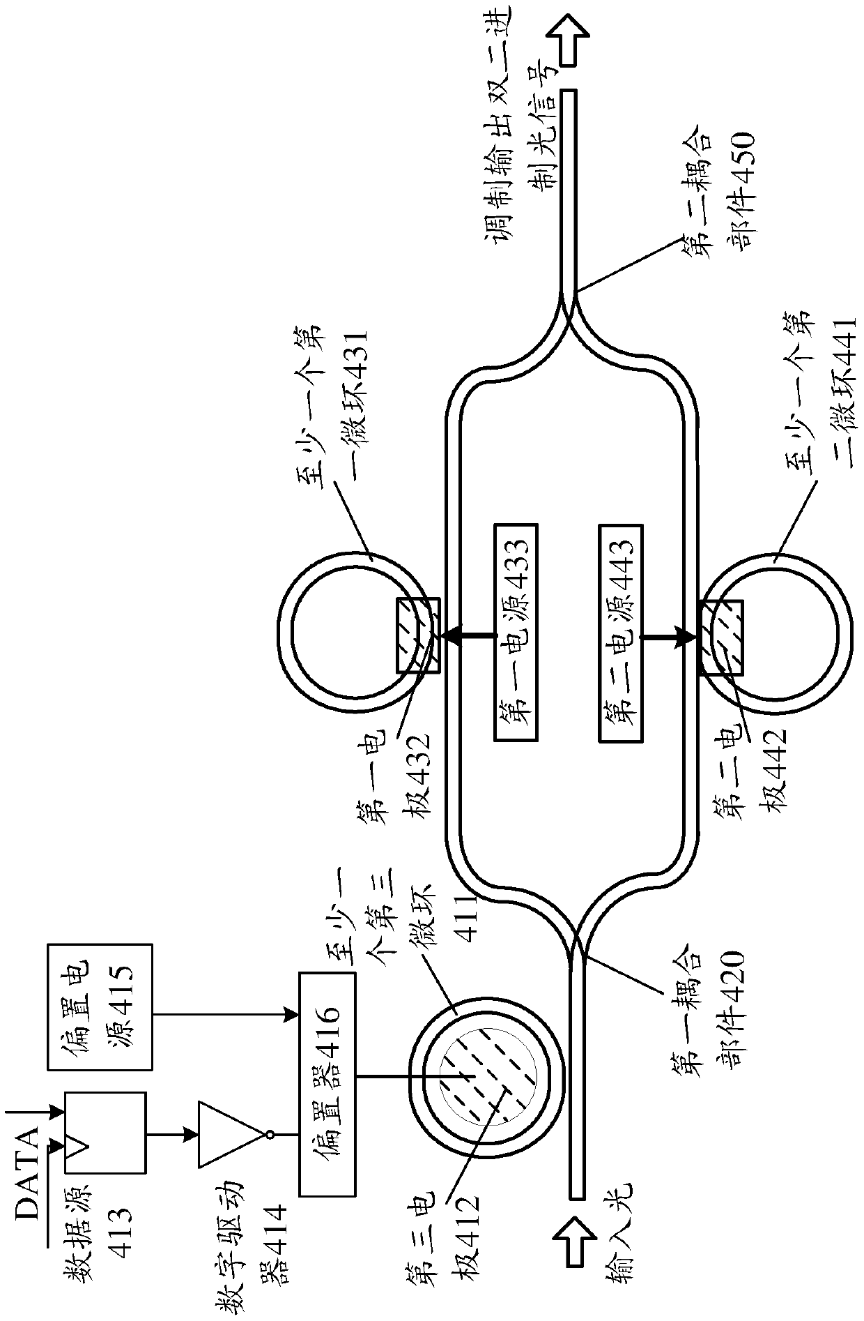
Provided by the embodiments of the present application is an apparatus and method for generating an optical signal, the apparatus comprising: a micro-ring modulator, configured for modulating a data signal into a first optical signal; a first coupling component, configured for coupling the first optical signal into two first optical signals; a first delay component, configured for generating a first optical delay amount for the first optical signal in the two first optical signals and outputting a second optical signal; a second delay component, configured for generating a second optical delay amount for the second first optical signal in the two first optical signals, and outputting a third optical signal, the difference between the first optical delay amount and the second optical delay amount being a delay amount corresponding to one bit; and a second coupling component, configured for coupling the second optical signal and the third optical signal into a duobinary optical signal. The apparatus for generating an optical signal of the embodiments of the present application may reduce the complexity of an apparatus generating a duobinary optical signal, thereby reducing cost.

Description

technical field [0001] The present application relates to the field of communication, and more particularly, to an apparatus and method for generating an optical signal. Background technique [0002] With the continuous progress and development of society, the amount of interactive information between people is increasing, so the amount of information data in the current society is increasing exponentially. The rapid development of the field of optical communication and optical network provides a reliable technical guarantee for the solution of this difficult problem. [0003] In the access network, the current mainstream technology is to use an optical access technology, Passive Optical Network ("PON" for short), and the PON network is a point-to-multipoint passive optical network system. There are many standards in the current PON network, mainly including Ethernet Passive Optical Network (Ethernet PON, referred to as "EPON"), Gigabit Passive Optical Network (Gigabit PON,...

Claims


Application Information

Patent Timeline
IPC IPC(8): H04J14/02
CPCH04J14/02
Inventor 戴竞吴朝叶志成
Owner HUAWEI TECH CO LTD
Learn More