Coil parts

A technology of coil components and coils, applied in transformer/inductor parts, electrical components, transformer/inductor coils/windings/connections, etc., can solve the problems of reduced inductance, high coupling coefficient, and difficulty in obtaining coupling coefficient, etc. Improve the effect of inductance

Active Publication Date: 2020-03-06
MURATA MFG CO LTD
View PDF6 Cites 0 Cited by
  • Summary
  • Abstract
  • Description
  • Claims
  • Application Information

AI Technical Summary

Problems solved by technology

If the internal magnetic circuit of the primary side coil and the internal magnetic circuit of the secondary side coil are arranged on the same straight line, the coupling coefficient will be very high, making it difficult to obtain the desired coupling coefficient (K)
On the other hand, if the internal magnetic circuit of the primary side coil and the internal magnetic circuit of the secondary side coil are not arranged on the same straight line, the coupling coefficient will be very low, making it difficult to obtain the desired coupling coefficient
In addition, since the core has an open magnetic circuit structure, the inductance (L) is reduced

Method used


Image

  • Coil parts
  • Coil parts
  • Coil parts

Examples


no. 1 approach

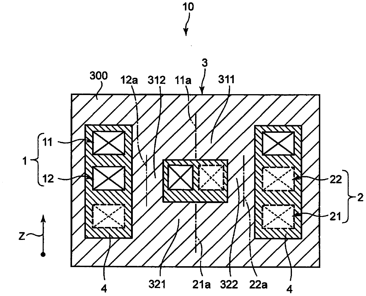
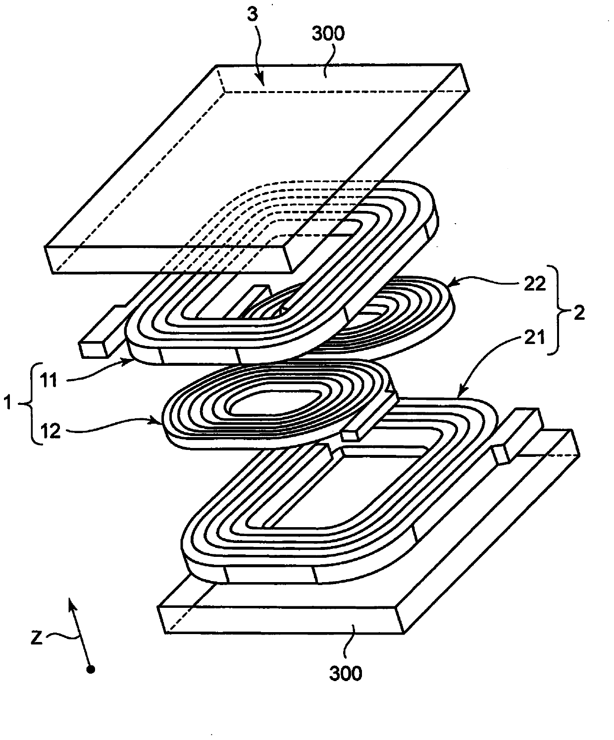
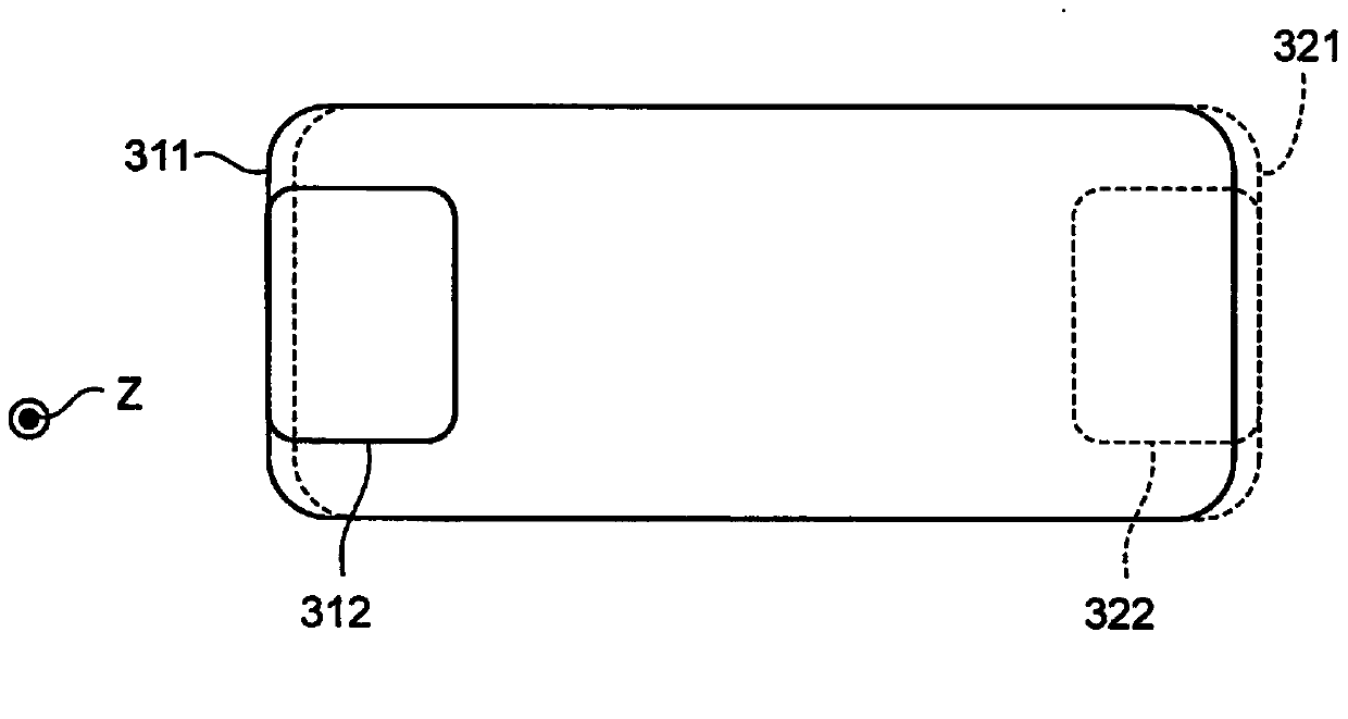
[0058] figure 1 It is a sectional view showing the first embodiment of the coil component of the present invention. figure 2 It is an exploded perspective view of the coil part. Such as figure 1 as well as figure 2As shown, the coil component 10 includes: a magnetic core 3 having a closed magnetic circuit structure; a primary side coil 1 wound around the magnetic core 3; and a secondary side coil 2 wound around the magnetic core 3 and disposed on the primary side. The axial direction of the side coil 1 and is magnetically coupled with the primary side coil 1 . The coil component 10 is used, for example, as a power filter choke coil (power choke coil). Primary side coil 1 and secondary side coil 2 are covered with insulating resin 4 . The insulating resin 4 is covered with the magnetic core 3 . Let the axial direction of the primary side coil 1 be a Z-axis direction. exist figure 1 The primary side coil 1 is shown by a solid line, and the secondary side coil 2 is show...

no. 2 approach

[0081] Figure 4 It is a sectional view showing the second embodiment of the coil component of the present invention. Figure 5 It is an exploded perspective view of the coil part. The second embodiment differs from the first embodiment in the configuration of the second coil portion of the primary side coil and the secondary side coil. Only this different structure will be described below. In addition, in the second embodiment, the same reference numerals as those in the first embodiment denote the same structures as those in the first embodiment, and therefore description thereof will be omitted.

[0082] Such as Figure 4 and Figure 5 As shown, in the coil component 10A, the second coil portion 12A of the primary side coil 1A has a first helical portion 121 and a second helical portion 122 . The first helical part 121 and the second helical part 122 are stacked sequentially from the first coil part 11 in the Z-axis direction. The first spiral portion 121 and the seco...

no. 3 approach

[0089] Figure 6 It is a cross-sectional view showing a third embodiment of the coil component of the present invention. The third embodiment differs from the first embodiment in the positions of the second coil portions of the primary side coil and the secondary side coil. Only this different structure will be described below. In addition, in the third embodiment, the same reference numerals as those in the first embodiment denote the same structures as those in the first embodiment, and therefore description thereof will be omitted.

[0090] Such as Figure 6 As shown, in the coil component 10B, the second coil portion 12 of the primary side coil 1 and the second coil portion 22 of the secondary side coil 2 are located in the Z-axis direction. In the Z-axis direction, the second coil portion 12 of the primary side coil 1 is located between the first coil portion 21 and the second coil portion 22 of the secondary side coil 2, and the second coil portion 22 of the secondary...


PUM

PropertyMeasurementUnit
particle sizeaaaaaaaaaa

Abstract

The present invention provides a coil component capable of increasing inductance and adjusting coupling coefficient. The coil component includes: a magnetic core having a closed magnetic circuit structure; a primary side coil wound on the magnetic core; coupling. The primary side coil and the secondary side coil each have a first coil portion and a second coil portion electrically connected to the first coil portion. The second coil portion overlaps the first coil portion in an axial direction of the first coil portion, and the axis of the second coil portion is eccentric with respect to the axis of the first coil portion. The cross-sectional area of ​​the internal magnetic circuit of the second coil unit in the direction perpendicular to the axis is smaller than the cross-sectional area of ​​the internal magnetic circuit of the first coil unit in the direction perpendicular to the axis.

Description

technical field [0001] The present invention relates to coil components. Background technique [0002] Conventionally, coil components include those described in US 6,362,986 B1 (Patent Document 1). The coil component includes: a magnetic core having an open magnetic circuit structure; a primary side coil wound around the magnetic core; and a secondary side coil wound around the magnetic core and magnetically coupled to the primary side coil. The internal magnetic circuit of the primary side coil and the internal magnetic circuit of the secondary side coil are arranged on the same straight line, or are not arranged on the same straight line. [0003] Patent Document 1: US 6,362,986 B1 [0004] However, when the above conventional coil components are actually used, the following problems are found. If the internal magnetic circuit of the primary side coil and the internal magnetic circuit of the secondary side coil are arranged on the same straight line, the coupling coeff...

Claims


Application Information

Patent Timeline
Patent Type & Authority Patents(China)
IPC IPC(8): H01F17/04H01F27/30
CPCH01F17/045H01F27/306H01F17/0013H01F27/2823H01F27/38H01F2017/0093H01F2017/048H01F27/255
Inventor 吉冈由雅西山健次滨田显德
Owner MURATA MFG CO LTD
Why Eureka
Try Eureka