Expansion reel mandrel

A movement, axial technology used in the field of fixing/clamping spreader segments and/or locking slats to solve problems such as production interruptions

Inactive Publication Date: 2008-07-09
SMS DEMAG AG
View PDF8 Cites 13 Cited by
  • Summary
  • Abstract
  • Description
  • Claims
  • Application Information

AI Technical Summary

Problems solved by technology

The wedge surface structure must be kept within a narrow range with regard to its frictional properties, because otherwise malfunctions such as jamming or self-moving segments under load can occur, which in turn lead to production interruptions

Method used


Image

  • Expansion reel mandrel

Examples


Embodiment Construction

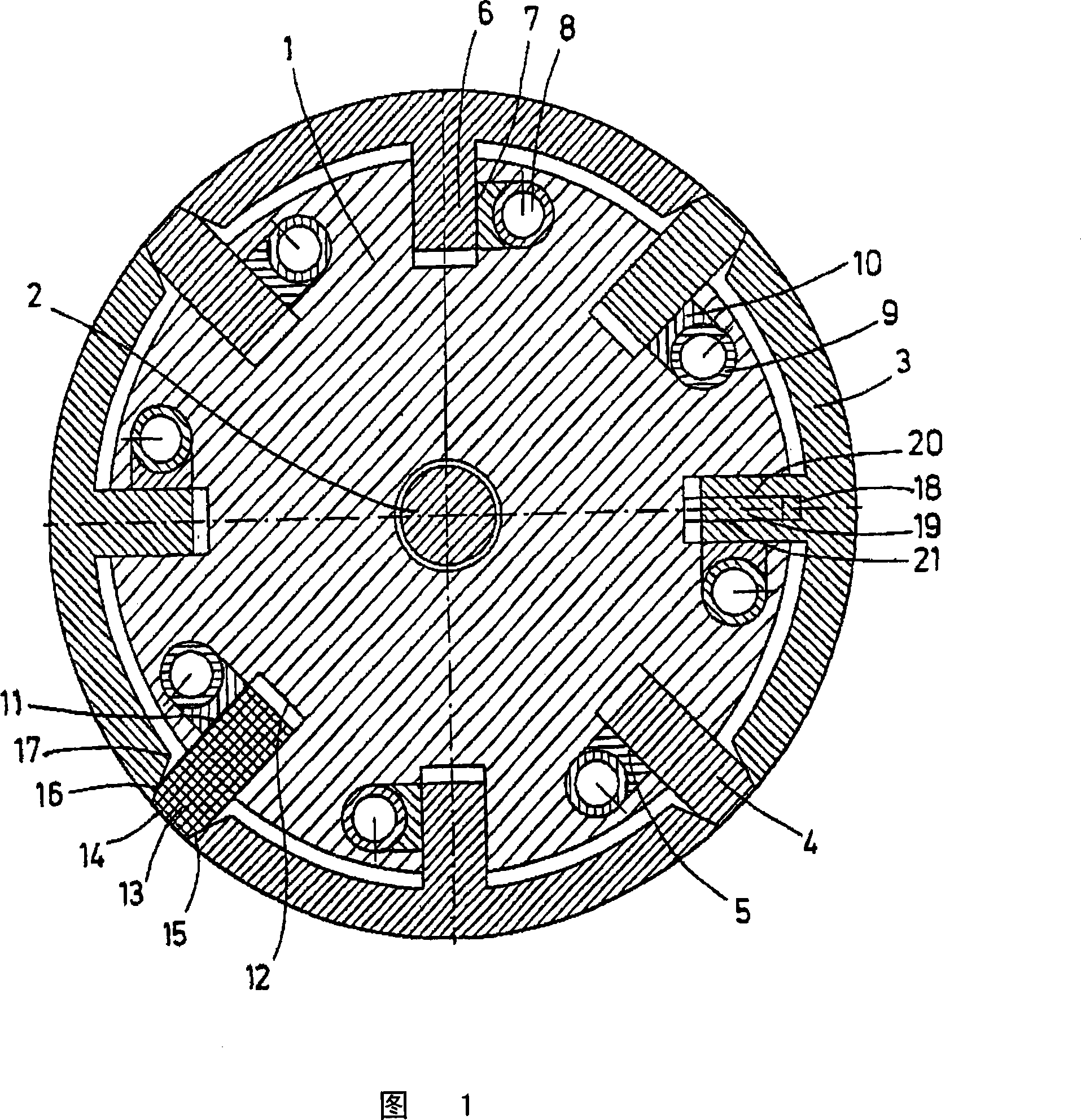
[0022] The single figure shows a cross-section of a coiler mandrel 1 which has an operating lever 2 in its central bore. The expansion segment 3 and the locking strip 4 are positioned radially in the guide groove 5 by means of the operating lever 2 . In this case, the expansion segments 3 and the locking strips 4 form a closed circle in the radially outer position. In the radially inner position, a gap is produced between the expansion segments 3 because the locking strips 4 are positioned radially further inward.

[0023] Each expansion segment 3 is held and guided in the guide groove 5 by means of a web 6 . In the side wall 7 of the guide groove 5, an axially extending hole 8 is incorporated. This hole 8 opens towards the guide groove 5 . Put the hose 9 into this hole 8 . In the embodiment shown, a clamping piece 10 is arranged between the hose 9 and the connecting piece 6 . In another embodiment, the hose 9 is in direct contact with the connecting piece 6 (not shown). ...


PUM


Abstract

The invention relates to a reel mandrel (1) comprising radially mobile expansion segments (2) and / or closing strips (4, 13) arranged on the periphery thereof. According to the invention, the reel mandrel (1) is provided with axially arranged guiding grooves (12) on the periphery thereof, and the expansion segments (2) are provided with ribs (6). The invention further relates to a method for fixing and / or maintaining an expansion segment (2) and / or a closing strip (3, 13) on a reel mandrel (1).

Description

technical field [0001] The invention relates to a coiler mandrel with radially displaceable expansion segments and / or locking slats arranged on the circumference and a method for fastening / clamping the expansion segments and / or locking slatted approach. Background technique [0002] Coiler devices are used, for example, to wind rolled sheet or other material into coils and / or to uncoil coils on coiler mandrels. For winding, the expansion segments are deflected radially outwards such that the outer circumference of the expansion segments forms a circle. In order to uncoil a roll, the coiler mandrel must be smaller in its diameter than the inner diameter of the roll for receiving it. Furthermore, usually two diameters can be used in a targeted manner on the coiler shaft, of which only the widened, largest diameter forms a full circle. [0003] In the disclosed embodiment of the coiler shaft, the coiler segments are radially deflected for this purpose by wedge-shaped surface...

Claims


Application Information

Patent Timeline
Patent Type & Authority Applications(China)
IPC IPC(8): B21C47/30
CPCB21C47/30B21C47/04B21C47/18
Inventor W·登克
Owner SMS DEMAG AG
Why Eureka
Try Eureka