
Liquid-jet head and liquid-jet apparatus having same

A liquid jet head, liquid technology, used in printing and other directions

Active Publication Date: 2011-02-16
SEIKO EPSON CORP
View PDF1 Cites 0 Cited by
  • Summary
  • Abstract
  • Description
  • Claims
  • Application Information

AI Technical Summary

Problems solved by technology

[0013] Moreover, this kind of problem exists not only in the inkjet recording head which ejects ink, but also in the liquid ejection head which ejects liquid other than ink.
Especially in liquid heads used for industrial purposes other than printing, there are many opportunities to eject high-viscosity liquids, so the above-mentioned problems become prominent.

Method used

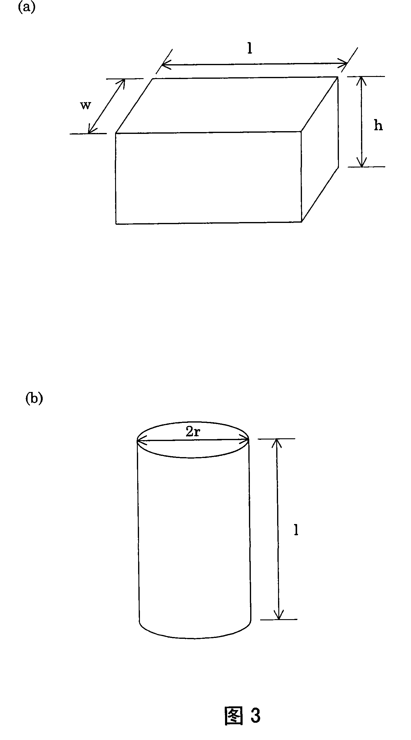

Image

  • Liquid-jet head and liquid-jet apparatus having same
  • Liquid-jet head and liquid-jet apparatus having same
  • Liquid-jet head and liquid-jet apparatus having same

Examples


no. 1 approach

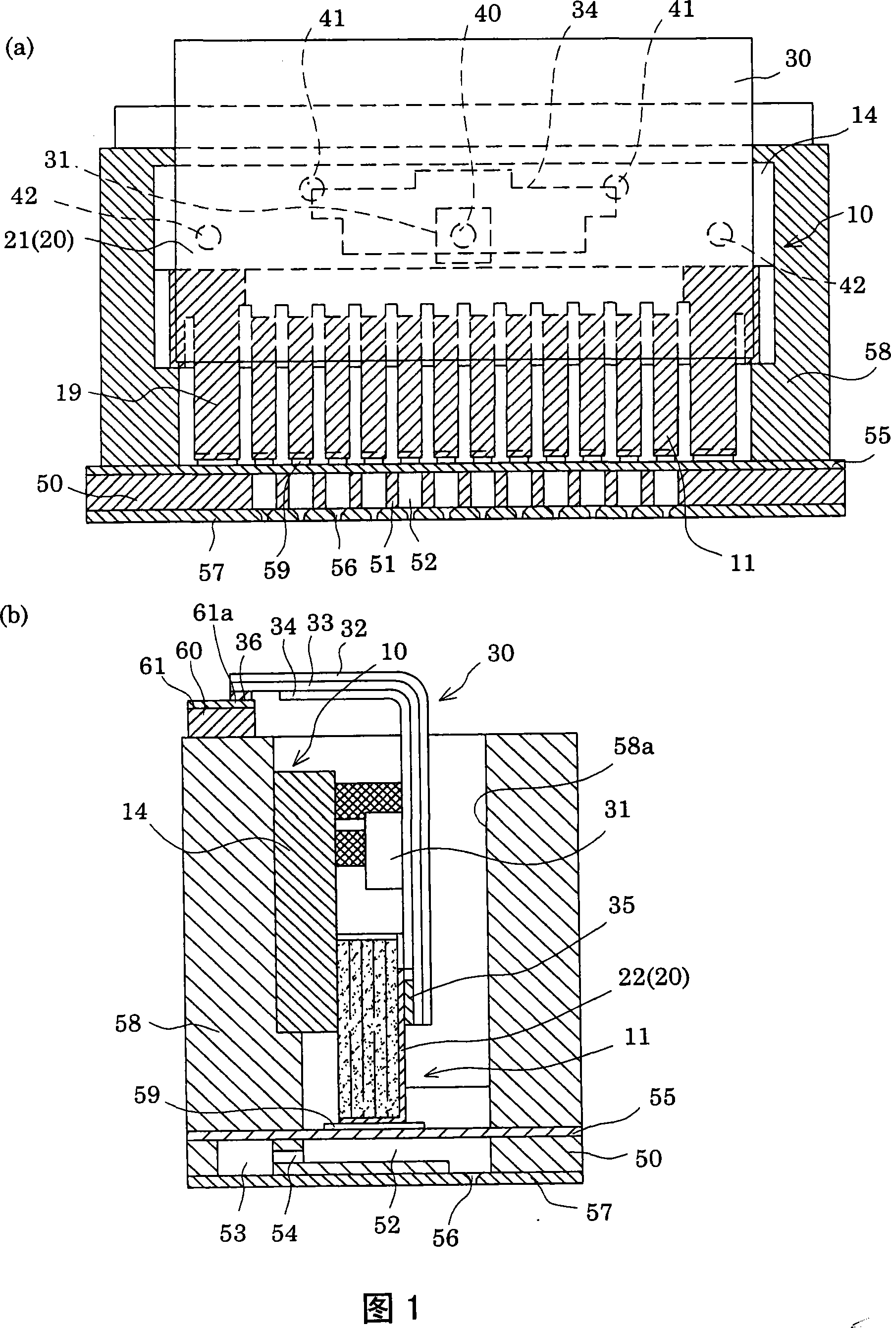
[0049] A head tank 58 having an ink supply path connected to a plurality of ink cartridges not shown is fixed to the vibrating plate 55 , and the piezoelectric element unit 10 is positioned and fixed with high precision in the head tank 58 . That is, the head box 58 is provided with a penetrating receiving portion 58a, and the piezoelectric element unit 10 is fixed on the inner surface of one side of the receiving portion 58a, and the front ends of each piezoelectric element 11 abut against the corresponding vibrating plate 55. Each island portion 59 on the area of ​​each pressure generating chamber 52 on the upper side.

[0050] In the above-mentioned ink jet recording head, the displacement of the piezoelectric element 11 accompanying the supply of the drive signal causes a pressure fluctuation in the pressure generating chamber via the vibrating plate 55, and the pressure generation chamber is filled with the pressure fluctuation using the pressure fluctuation. Ink within c...


PUM


Abstract

The invention provides a liquid injection head, capable of making sure an sufficient ejecting quantity even in the condition for using a liquid with a high viscosity, and the liquid injection head with a good meniscus after injecting is in favor of the speed-up for printing. The liquid injection head comprises a pressure chamber which supplies liquid through a liquid supplying pass and forms a nozzle for injecting the liquid; a piezoelectric element which produces a pressure change in the pressure chamber, wherein, when the inertia and the flow path impedance of the liquid supplying pass is supposed to be M1 and R1 respectively, and the inertia and the flow path impedance of the nozzle is supposed to be M2 and R2 respectively, the relationships come into existence, that is M2<M1, R2>2R1.

Description

technical field [0001] The present invention relates to a liquid ejection head and a liquid ejection device having the same, and is particularly useful when it is suitable for use of a high-viscosity liquid. Background technique [0002] As a liquid ejecting device, there is an ink jet recording device provided with an ink jet recording head having, for example, a plurality of pressure generators that generate a pressure to eject the liquid using a pressure generating mechanism composed of a piezoelectric element. chambers; an ink supply path for individually supplying ink from a common storage chamber to each of the pressure generating chambers; and a nozzle opening for ejecting ink droplets formed in each of the pressure generating chambers. In the above-mentioned inkjet recording device, energy is applied to ink in a pressure generating chamber communicating with a nozzle corresponding to a printing signal, so that ink droplets are ejected from the nozzle opening. [00...

Claims


Application Information

Patent Timeline
Patent Type & Authority Patents(China)
IPC IPC(8): B41J2/14B41J2/045
Inventor 张俊华
Owner SEIKO EPSON CORP
Learn More