
Liquid-jet head and liquid-jet apparatus having same

A liquid ejection head, liquid technology, applied in printing and other directions, can solve the problems of slow return, high-viscosity liquid ejection opportunities, etc.

Active Publication Date: 2008-07-16
SEIKO EPSON CORP
View PDF1 Cites 10 Cited by
  • Summary
  • Abstract
  • Description
  • Claims
  • Application Information

AI Technical Summary

Problems solved by technology

[0012] Referring to Figure 24, it can be seen that when the viscosity of the ink shown in Figure (a) is 5.0 (mPa·s), 12 (ng) ink droplets are ejected, and the return after ejection is fast enough, but in the case of When the viscosity of the ink shown in figure (b) is 10.0 (mPa·s), only 10 (ng) ink droplets can be ejected, and the return after ejection is also very slow.
[0013] Moreover, this kind of problem exists not only in the inkjet recording head which ejects ink, but also in the liquid ejection head which ejects liquid other than ink.
Especially in liquid heads used for industrial purposes other than printing, there are many opportunities to eject high-viscosity liquids, so the above-mentioned problems become prominent.

Method used


Image

  • Liquid-jet head and liquid-jet apparatus having same
  • Liquid-jet head and liquid-jet apparatus having same
  • Liquid-jet head and liquid-jet apparatus having same

Examples


no. 1 approach

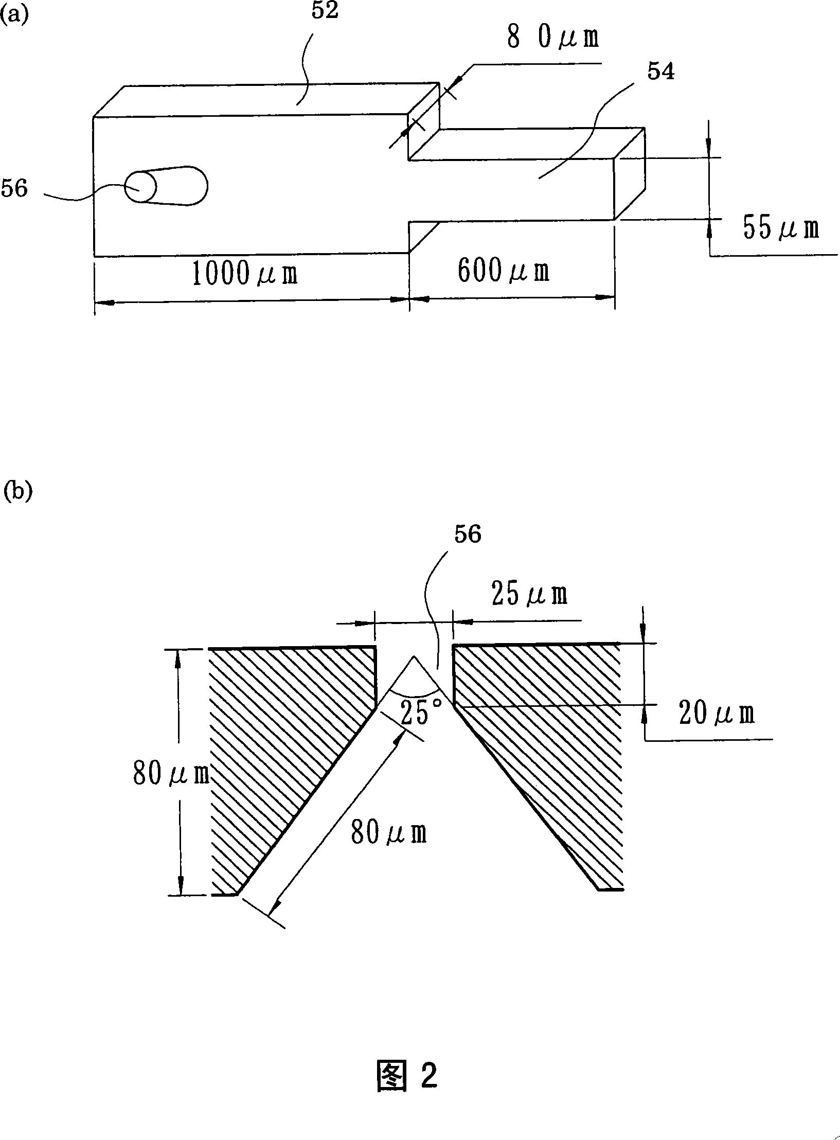
[0048] 1( a ) is a cross-sectional view in the short side direction of a pressure generating chamber of an ink jet recording head as an example of a liquid ejecting head according to an embodiment of the present invention, and FIG. 1( b ) is an example of a liquid ejecting head. A longitudinal cross-sectional view of the pressure generating chamber of the inkjet recording head. As shown in both figures, the flow path forming substrate 50 is composed of a silicon single crystal substrate, and pressure generating chambers 52 formed of a plurality of partition walls 51 are arranged side by side along the width direction (short side direction) of the surface layer on one side. In addition, a storage chamber 53 for supplying ink, which is a kind of liquid, to each pressure generating chamber 52 communicates with one end in the longitudinal direction of each pressure generating chamber 52 via an ink supply path 54 that is a type of liquid supply path. . In addition, the opening sid...


PUM


Abstract

The present invention provides a liquid ejection head that can ensure a sufficient amount of ejection even when a high-viscosity liquid is used, and is advantageous in high-speed printing as a liquid ejection head that can ensure a good meniscus behavior after ejection. change. The liquid ejecting head has a pressure generating chamber (52) which supplies liquid through a liquid supply path (54) and is formed with a nozzle opening (56) for ejecting the liquid; a piezoelectric element (11) which generates the pressure. Pressure changes occur in the chamber (52), when the inertia and flow path impedance of the liquid supply path (54) are respectively set as M1 and R1, the inertia and flow path impedance of the nozzle opening (56) are respectively set as M2 , R2, the relationship of M2<M1 and R2>2R1 is established.

Description

technical field [0001] The present invention relates to a liquid ejection head and a liquid ejection device having the same, and is particularly useful when it is suitable for use of a high-viscosity liquid. Background technique [0002] As a liquid ejecting device, there is an ink jet recording device provided with an ink jet recording head including, for example, a plurality of pressure generators that generate pressure for ejecting liquid using a pressure generating mechanism composed of a piezoelectric element. chambers; an ink supply path for individually supplying ink from a common storage chamber to each of the pressure generating chambers; and a nozzle opening for ejecting ink droplets formed in each of the pressure generating chambers. In the above-mentioned inkjet recording device, energy is applied to ink in a pressure generating chamber communicating with a nozzle corresponding to a printing signal, so that ink droplets are ejected from the nozzle opening. [00...

Claims


Application Information

Patent Timeline
Patent Type & Authority Applications(China)
IPC IPC(8): B41J2/14B41J2/045
Inventor 张俊华
Owner SEIKO EPSON CORP
Learn More