Cylinder type workpiece code word machine

A type code machine, cylindrical technology, applied in the field of code type machines for cylindrical workpieces, can solve the problems of heavy maintenance workload, difficult hydraulic system troubleshooting, poor practicability, etc.

Inactive Publication Date: 2008-07-16
李钢放
View PDF2 Cites 17 Cited by
  • Summary
  • Abstract
  • Description
  • Claims
  • Application Information

AI Technical Summary

Problems solved by technology

It has the problems of difficult troubleshooting of the hydraulic system and a large workload for maintenance. For this reason, a Chinese patent once disclosed a "character rolling machine for cylindrical workpieces that adopt mechanical transmission" (CN2820532Y, announcement date 2006.09.27). It includes an organic table and a bar-shaped font. It also includes a gear shaft and a workpiece support frame. The two ends of the gear shaft are placed in the gear shaft installation holes on the upper part of the machine table. The upper surface of the bar-shaped font is fixed with a rack. The gear of the gear shaft meshes with the rack fixed on the upper surface of the bar type, and the workpiece support frame is fixed on the machine below the gear shaft
Although it avoids the problems of hydraulic transmission, it is poor in practicability. There is no such type of "character rolling machine for cylindrical workpieces with mechanical transmission" on the market.

Method used


Image

  • Cylinder type workpiece code word machine
  • Cylinder type workpiece code word machine

Examples


Embodiment Construction

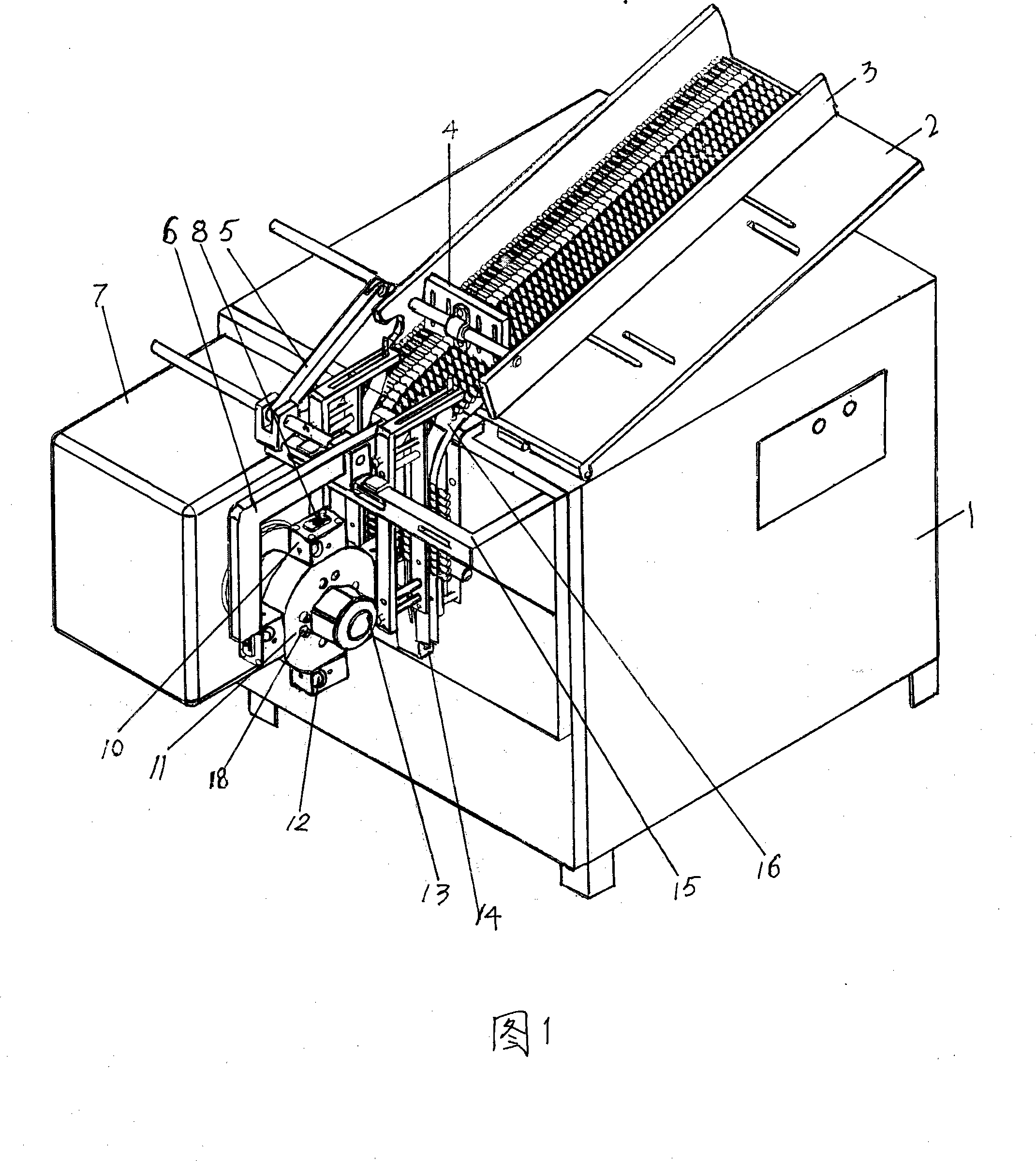
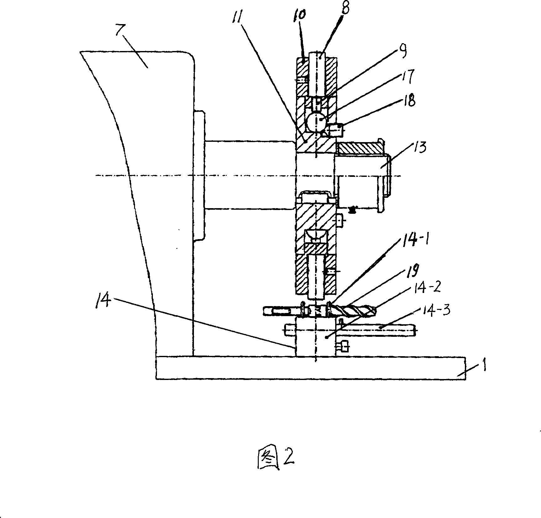
[0009] The present invention will be further described below in conjunction with the embodiments and accompanying drawings.

[0010] Referring to Fig. 1, a cylindrical workpiece coding machine, the body 1 has a built-in motor and its gearbox, the body 1 is obliquely mounted with an adjustable bracket 2, and the width-adjustable hopper 3 is mounted on the adjustable bracket 2, and the width can be adjusted. The front of the seasoning hopper 3 is connected to the curved material channel 16, and the front end of the width-adjustable hopper 3 is provided with a material pulling mechanism 4. The main shaft box 7 is fixed on one side of the front side of the fuselage 1, and the main shaft box 7 supports the main shaft 13. The gearbox drives the main shaft 13, and the front end of the main shaft 13 Fixed roller 11, at least one font box 10 is fixed around the roller 11, letter pattern mold 8 is embedded in the font box 10, cam 12 is equipped with on one side of font box 10, and specia...


PUM


Abstract

The invention relates to a cylindrical workpiece code machine. A machine body is internally provided with a motor and a gear box, and is provided with an adjustable frame slantwise and fixed with a headstock at one side in the front; the front part of the hopper which is arranged on the adjustable frame is connected with a curved feed channel while a feed puller mechanism is positioned on the front end thereof; the headstock supports a cardinal axis which is driven by the gear box; a rolling wheel is fixed at the front end of the cardinal axis and with at least a character mold box at the four sides; character patterns are inlaid in the character mold box one side of which is provided with a cam; a special-shaped gasket mechanism is fixed at the other side in the front of the machine body and under the curved feed channel; a regulating frame which is provided with a feeding rack is fixed at the front end of the machine body and a feed puller driving rack is arranged on the regulating frame; when the cardinal axis is rotating, the cam drives the feeding rack with which the feed puller driving rack is contacted and interlocked while the feed puller driving rack is contacted with and drives the feed puller mechanism. By adopting the code machine of the invention, the cut character is neat and clear, with high production efficiency.

Description

technical field [0001] The invention relates to a machine for rolling out character patterns on the surface of a cylindrical workpiece, in particular to a coding machine for a cylindrical workpiece. Background technique [0002] Cylindrical products such as electric hammer drills, impact drills, twist drills, and copper sleeve hole openers need to print specification numbers, trademarks, serial numbers and other markings and patterns on the surface of the cylinder. At present, this work is done by hand, that is, by prefix tapping. Although this method is simple, it is labor-intensive and extremely inefficient. Due to unstable hand holding and uneven force, the characters and patterns are of different shades, unevenly arranged, and blurred, which brings a lot of inconvenience to recognition and use, and affects the quality of products and products. negative impact on corporate image. A Chinese patent once disclosed a "cylinder type rolling machine" (CN269858 1Y, announcemen...

Claims


Application Information

Patent Timeline
Patent Type & Authority Applications(China)
IPC IPC(8): B41K3/22B41K3/44
Inventor 李钢放
Owner 李钢放
Why Eureka
Try Eureka