Semi-free piston linear generator set

A technology of generating sets and generators, which is applied in the direction of electric components, engine components, machines/engines, etc., can solve the problems of system work impact, high stress strength of crank connecting rod mechanism, complex control system, etc., and achieve high power output efficiency , solve the effect of working condition stability and simple control system

Inactive Publication Date: 2010-06-09
潍坊威度电子科技有限公司
View PDF1 Cites 0 Cited by
  • Summary
  • Abstract
  • Description
  • Claims
  • Application Information

AI Technical Summary

Problems solved by technology

The conversion and transmission route of heat energy to electricity is long, the efficiency is low, and energy waste is serious
②Because the piston in the system is directly connected to the crank connecting rod mechanism, the swing of the connecting rod causes a large lateral force of the piston, which not only causes a loss of mechanical efficiency, but also causes wear and additional thermal load between the piston and the cylinder wall; ③ crank The connecting rod mechanism participates in the transmission and conversion of all power, the crank connecting rod mechanism has a large stress strength, the friction loss at each hinge point is serious, and the unevenness of the system operation is large
④The crankshaft and connecting rod system is complex and bulky, the waste of raw materials is serious, and the production cost and operation cost are high
[0004] ①The start-up system is complicated, the auxiliary system is difficult to drive, and it is difficult to realize timing and coordination work; it is difficult to realize the 4-stroke working mode and multi-cylinder linkage
[0005] ② There is no fixed dead point, no fixed stroke, and the compression ratio is variable. Although it is easy to improve the combustion process of the engine by adjusting the compression ratio, it is difficult to control the stability of the working condition; at the same time, in order to pursue high efficiency and low emissions, it is required to accurately adjust the compression ratio control, making the control system more complex and difficult to solve
[0006] ③The fuel supply timing structure is complex, resulting in uncertain control of compression ratio, combustion pressure, etc., and the control accuracy of circulating fuel supply is much higher than that of traditional engines, which brings difficulties in the manufacture of fuel supply systems
[0007] ④The motion characteristics of the moving parts are non-sinusoidal. The piston movement is asymmetrical near the dead point, and the deceleration section is longer than the acceleration section. Compared with the traditional system, the thermal energy-mechanical energy and mechanical energy-electricity conversion environment has changed. It is difficult to directly realize the working characteristics and performance of traditional systems
Due to the unbalanced structure, the reciprocating inertial force cannot be self-balanced, resulting in increased shock and instability of the system, and the resulting vibration problem needs to be solved by additional means;
[0009] ⑥Because the piston is "free", it is difficult to adjust the speed; because there is no flywheel, the engine stalls seriously, resulting in poor engine reliability

Method used


Image

  • Semi-free piston linear generator set
  • Semi-free piston linear generator set
  • Semi-free piston linear generator set

Examples


Embodiment 1

[0048] Examples of linked power generation units in the form of piston structures are as follows.

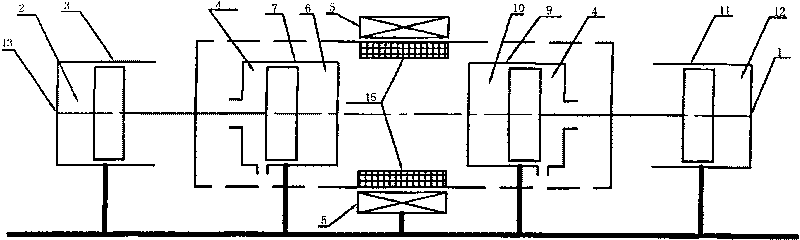
[0049] figure 2 Among them, the first cylinder 3 , the second cylinder 7 , the third cylinder 9 and the fourth cylinder 11 are axially and concentrically mounted on the support member 18 . The first cylinder head 13 and the fourth cylinder head 1 face outward ( figure 2 shown in the left and right respectively), the second cylinder head 17 and the third cylinder head 19 are opposite, close to the generator stator and winding 5. The rear parts of the second cylinder 7 and the third cylinder 9 respectively have an air cushion chamber 4 and associated sealing and auxiliary air passages 14 . The generator stator and winding 5 are also installed on the support member 18, which is symmetrical with respect to the axis of the cylinder and located at the axial center of the whole device.

[0050] attached image 3 As shown, the first piston 22 and the second piston 24 are integrate...

Embodiment 2

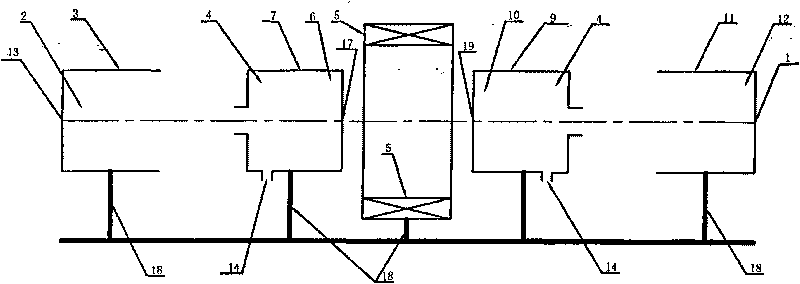
[0059] An example of a linkage generating unit in the form of a fixed plug structure is as follows.

[0060] attached Figure 5 As shown, the fixed plug 8 includes a second fixed plug 25 and a third fixed plug 26, which are installed on the support member 18 between the two generator stators and the winding 5. The fixed plug 8 is equipped with auxiliary components such as air passages, air valves, and ignition required by the second combustion chamber 6 and the third combustion chamber 10 . The tails of the first cylinder 3 and the fourth cylinder 11 respectively have a sealing structure associated with the auxiliary cylinder chamber 4 and an auxiliary air channel 14 . The generator stator and winding 5 are also installed on the support member 18, which is symmetrical with respect to the axis of the cylinder, divided into two parts and corresponding to the mover shaft 16 respectively.

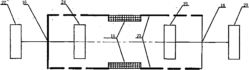
[0061] attached Image 6 As shown, the two generator movers 15 are respectively installe...


PUM


Abstract

The invention discloses a quasi-free piston linear generator set, which solves the problems that the existing power free piston engine has complex structure and unreliable work, etc. The invention hasthe advantages of simple structure, convenient application, good reliability of work, etc. The structure of the invention comprises at least a generation unit and a corresponding fuel supply and airinlet and exhaust system; the generation unit is a linkage generation unit which is formed by a group of a cylinder and a piston which are matched with each other and correspondingly motion linearly;the rotor of the generator is connected with the motion part of the linkage generation unit; the stator and the winding of the generator are connected with the fixed part of the linkage generation unit; meanwhile, the motion end point of the linkage generation unit is provided with a retaining part which is used for restraining the stroke of the motion part; the stator and the winding of the generator can be taken as the output terminal of the power.

Description

technical field [0001] The invention belongs to the technology of converting heat energy to electric energy of an internal combustion type power device, and in particular relates to a quasi-free piston linear generator set. Background technique [0002] In the traditional internal combustion engine-generator set, the heat energy released by fuel combustion is first converted into the reciprocating linear mechanical power of the piston through the piston-cylinder part of the piston internal combustion engine, and then the reciprocating linear mechanical power of the piston is converted into Rotating mechanical power, and then the rotating mechanical power passes through several intermediate links such as couplings, splitters, etc., mechanical power transmission, shunting and transformation of power parameters, and finally converts mechanical energy into electricity through a rotating generator. This combined system is widely used, but it has the following obvious disadvantage...

Claims


Application Information

Patent Timeline
Patent Type & Authority Patents(China)
IPC IPC(8): F02B63/04H02K7/18H02K35/02F01L1/34
Inventor 孙军李澎
Owner 潍坊威度电子科技有限公司
Why Eureka
Try Eureka