Rotating damper

A technology for rotating dampers and rotating shafts, which is applied in the direction of shock absorbers, shock absorbers, liquid shock absorbers, etc., and can solve the problems of large braking torque, large influence of braking torque, and non-rotating shafts, etc. To achieve the effect of reducing torque variation

Inactive Publication Date: 2008-07-16
NIFCO INC
View PDF0 Cites 1 Cited by
  • Summary
  • Abstract
  • Description
  • Claims
  • Application Information

AI Technical Summary

Problems solved by technology

[0008] However, even if the self-lubricating silicone rubber is used to form the sealing material, since the silicone oil penetrates the sealing material, and the housing and the rotating shaft are in contact with the sealing material, resistance caused by the silicone oil penetrating into the sealing material is generated when the rotating shaft rotates. The low temperature has a great influence on the braking torque, for example, the braking torque becomes larger and the shaft does not rotate

Method used


Image

  • Rotating damper
  • Rotating damper
  • Rotating damper

Examples


Embodiment Construction

[0027] Embodiments of the present invention will be described below with reference to the drawings.

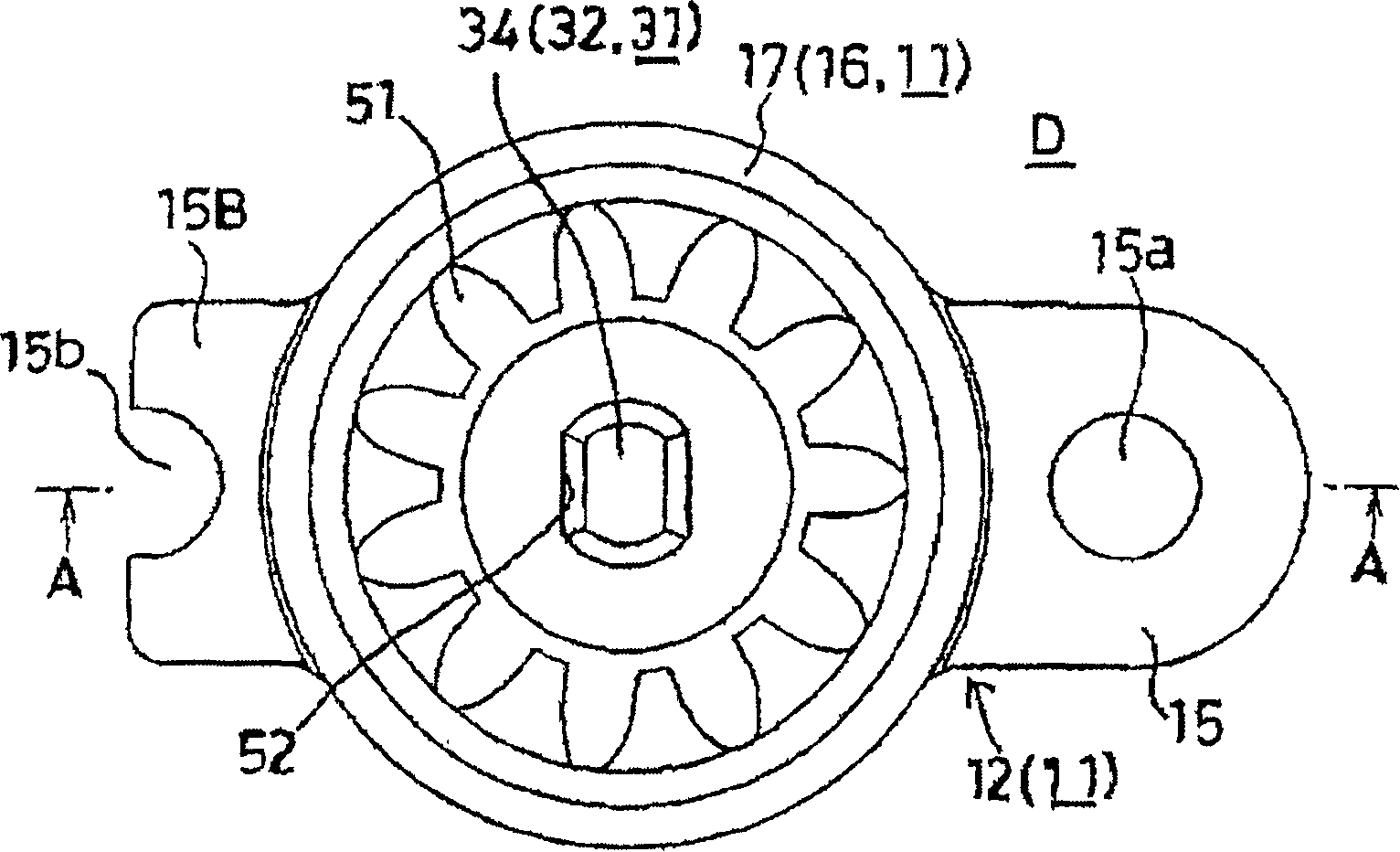
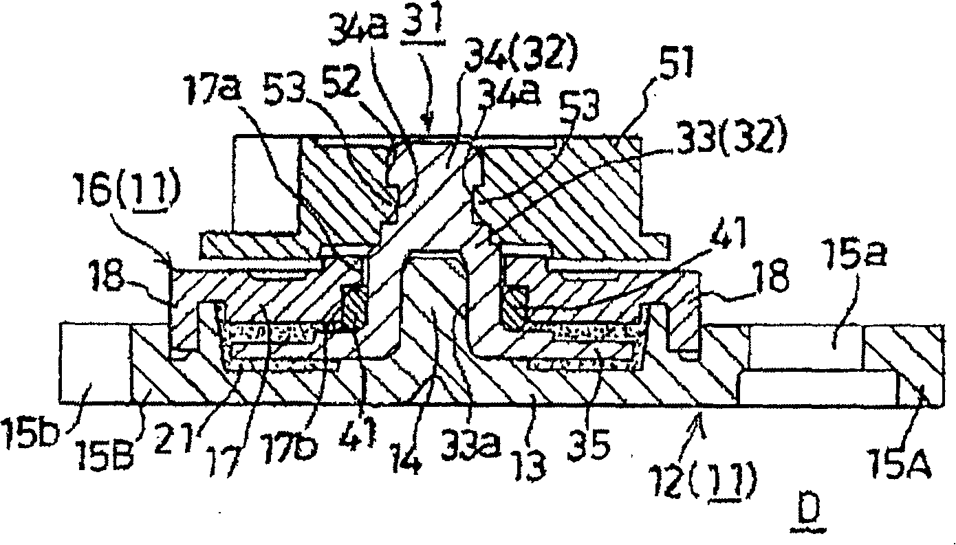
[0028] figure 1 is a plan view of a rotary damper as an embodiment of the present invention, figure 2 is along figure 1 Sectional view of line A-A.

[0029] In these figures, the composition of the rotary damper D includes: a casing 11; silicone oil 21 as a viscous fluid filled in the casing 11; a rotating shaft 32 having a part protruding from the casing 11; The rotor 31 of the rotor brake plate 35 is continuously arranged and rotatably accommodated in the housing 11; an O-ring as a sealing material is provided between the housing 11 and the rotating shaft 32 and prevents the silicon oil 21 from leaking out of the housing 11 41 ; the driven gear 51 installed on the portion of the rotating shaft 32 protruding from the housing 11 .

[0030] The housing 11 is composed of a housing main body 12 molded from synthetic resin and a cap 16 molded from synthetic resin.

[0031] M...


PUM


Abstract

The invention provides a rotation damper which can reduce the torque change which is caused by the correspondence of a sealing material to the change of the temperature and can be applied without poor conditions in cold areas. The structure of a rotation damper (D) comprises a shell (11), a silicon oil (21) which is filled into the shell (11), a rotor (31), a rotation shaft (32) with one part convex out of the shell (11), a rotor brake plate (35) which is continuously arranged at the lower end of the rotation shaft (32) and can be rotatablely arranged in the shell (11), and an O-shaped ring (41) which is arranged between the shell (11) and the rotation shaft (32) and can prevent the silicon oil (21) from being leaked out of the shell (11); wherein, the O-shaped ring (41) is formed by an ethylene-propylene-diene rubber which has non-expansibility to the silicon oil (21).

Description

technical field [0001] The present invention relates to a rotary damper that brakes the rotation of, for example, a driven gear that meshes with a gear and a rack. Background technique [0002] The composition of the above-mentioned rotary damper includes: a casing; a viscous fluid filled in the casing; a rotor having a rotating shaft protruding from the casing and a rotor system continuously arranged at the lower end of the rotating shaft and rotatably accommodated in the casing. a moving plate; and a sealing material disposed between the casing and the rotating shaft and preventing the viscous fluid from leaking out of the casing. [0003] Furthermore, a driven gear is integrally and rotatably attached to the portion of the rotating shaft protruding from the housing. [0004] In this rotary damper, silicone oil used as a viscous fluid has little change in viscosity (viscosity) due to temperature change and is suitable as a material for applying braking torque to the rotor...

Claims


Application Information

Patent Timeline
Patent Type & Authority Applications(China)
IPC IPC(8): F16F9/36F16F9/30F16F9/12
Inventor 西山雅幸
Owner NIFCO INC
Why Eureka
Try Eureka