Passively rephasing piston

A piston and piston body technology, applied in the field of passive re-phasing pistons, can solve problems such as unsatisfied and achieve reliable re-phasing effects

Inactive Publication Date: 2012-12-05
CLARK EQUIP CO INC
View PDF1 Cites 0 Cited by
  • Summary
  • Abstract
  • Description
  • Claims
  • Application Information

AI Technical Summary

Problems solved by technology

However, in some applications there is often a need for an alternative solution that has long been unmet

Method used


Image

  • Passively rephasing piston
  • Passively rephasing piston
  • Passively rephasing piston

Examples


Embodiment Construction

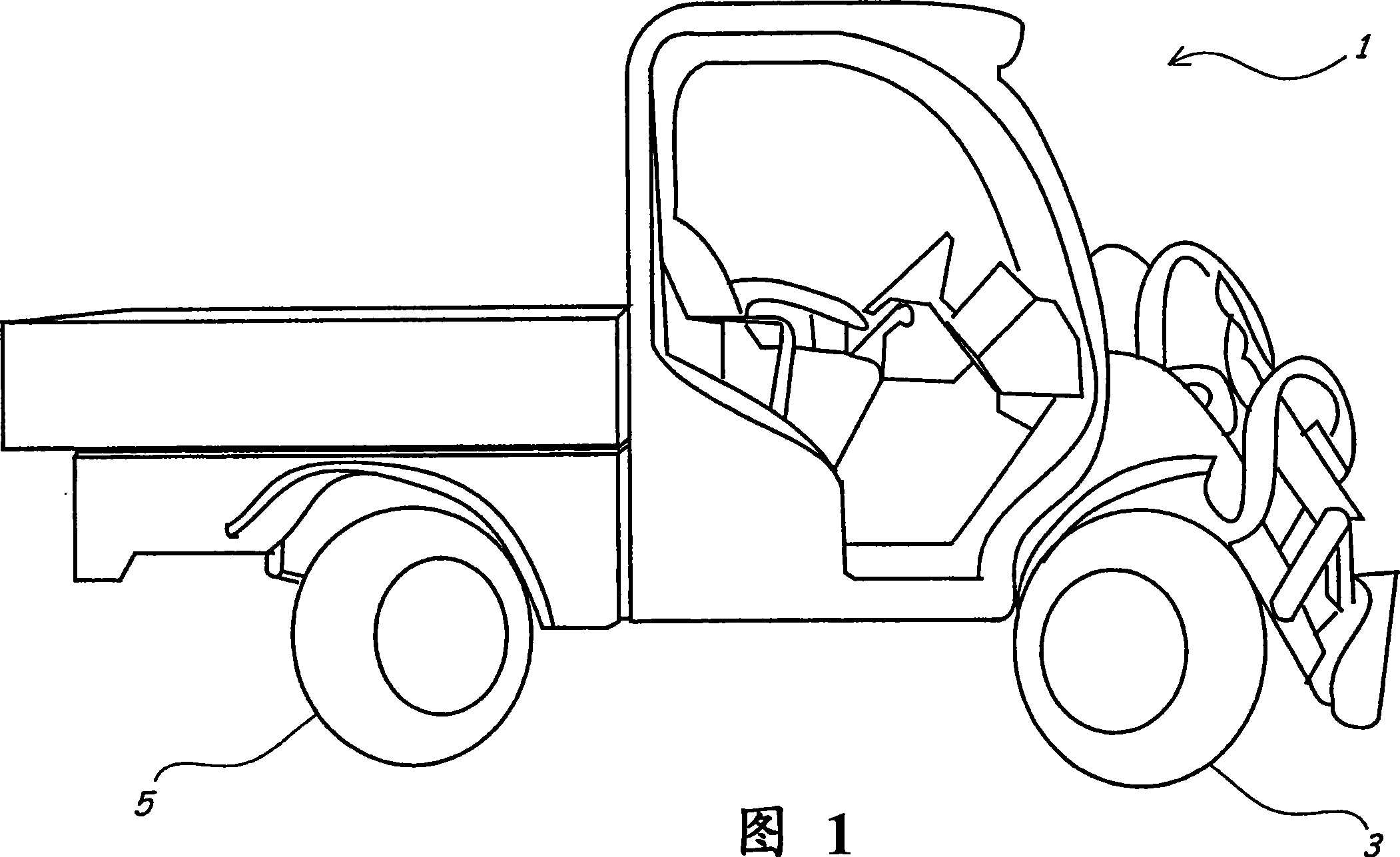
[0018] figure 1 A four wheel steerable vehicle 1 that may employ the fluid system of the present invention is described. The vehicle 1 comprises a pair of front steering wheels and a pair of rear steering wheels. The front steering wheel is controlled by the front rudder hydraulic cylinder, and one of the front steering wheels is wheel 3 as seen in the figure. The rear steering wheel is controlled by the rear rudder hydraulic cylinder, and one of the rear steering wheels is the visible wheel 5 among the figures. When controlling vehicle 1 to turn left, the front wheels will turn left while the rear wheels turn right. vice versa. Vehicle 1 is controlled to turn right, with the front wheels turning right and the rear wheels turning left. The four-wheel steering vehicle 1 has a smaller turning radius and other advantages compared with other vehicles that only use front or rear wheels for steering. The four wheel steer vehicle 1 is but one example of a wide variety of applic...


PUM


Abstract

A piston (302) is disclosed that includes a longitudinal passage (321) disposed between outlets on the opposing faces of the piston, and a radial passage (325) extending from a node with the longitudinal passage to an outlet on the annular wall between opposing piston seals. Check valves (331,333) are disposed in the longitudinal passage between the node and each of the piston faces, such that each of the check valves enables fluid flow from its inlet to the outlet on the annular wall, and block fluid flow from the outlet on the annular wall to the inlet. In the event of pistons in a fluid system becoming out of phase with each other, fluid may be admitted through the inlet of the longitudinal passage and the respective check valve and out a side wall outlet, thereby bypassing the piston to exit via the respective end port, until another, out-of-phase piston or pistons in the system also reach full extension or retraction, automatically returning all pistons in the system to be in phase with each other.

Description

[0001] Related Patent Applications [0002] The US prior application corresponding to this application enjoys the priority of US Patent Application No. 11 / 087338, the title of which is "Self-Synchronizing Hydraulic System", and the filing date is March 23, 2005. The disclosure of this US patent application is incorporated by reference in this prior US application. technical field [0003] The present invention relates to a fluid system, and more particularly to a passive rephasing piston. Background technique [0004] Hydraulic systems that provide pressurized flow to multiple hydraulic cylinders have provided an important solution for a large number of applications. For example, steering systems for vehicles have conventionally employed hydraulic systems in which extension and retraction of hydraulic cylinders drive wheels or other steering components to turn. In this system, in the case of a single rod cylinder, pressurized flow is supplied alternately to the base end a...

Claims


Application Information

Patent Timeline
Patent Type & Authority Patents(China)
IPC IPC(8): F16J1/00F16J1/09F15B15/14F15B11/22B62D5/06
CPCF15B2211/7121B62D5/12F15B11/22F15B15/149F15B15/204B62D5/061B62D7/142
Inventor 丹尼尔·J·克里基马修·R·凯那
Owner CLARK EQUIP CO INC
Why Eureka
Try Eureka