
Light source module structure and light tube rack using the same

A technology of light source module and lamp tube, which is applied in the direction of light source fixation, optics, nonlinear optics, etc., and can solve problems such as difficult alignment between reflector and frame, deformation of frame and reflector, and high equipment cost

Inactive Publication Date: 2008-07-16
AU OPTRONICS CORP
View PDF0 Cites 2 Cited by
  • Summary
  • Abstract
  • Description
  • Claims
  • Application Information

AI Technical Summary

Problems solved by technology

The existing technology of secondary injection molding requires high equipment cost, and the material of the frame body and the reflection sheet has different stresses, so that the injected frame body and the reflection sheet are easily pulled and deformed.
In addition, in the above technologies, no matter in the pasting process or the injection molding process, there may be misalignment due to the difficulty in aligning the reflective sheet with the frame

Method used


Image

  • Light source module structure and light tube rack using the same
  • Light source module structure and light tube rack using the same
  • Light source module structure and light tube rack using the same

Examples


Embodiment Construction

[0031] In a preferred embodiment, the present invention provides a light source module structure capable of effectively fixing the reflector on the frame and the lamp tube frame used therein. In a preferred embodiment, the structure of the light source module is used for the backlight module in the display device. For example, display devices include household televisions, screens of personal computers and laptop computers, display screens of mobile phones and digital cameras, and the like. However, in different embodiments, this light source module structure can also be applied to kanban and other devices that require light sources.

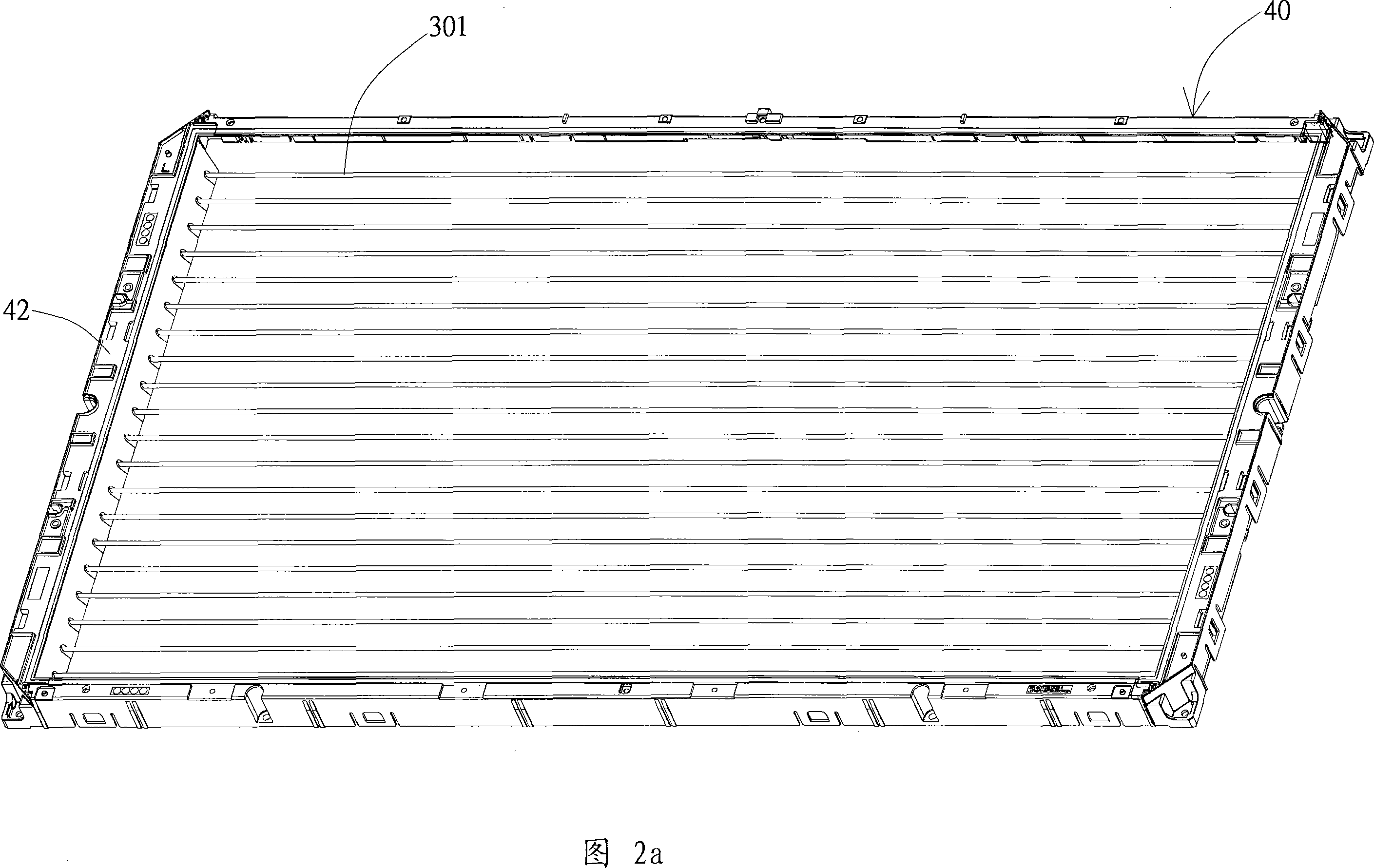
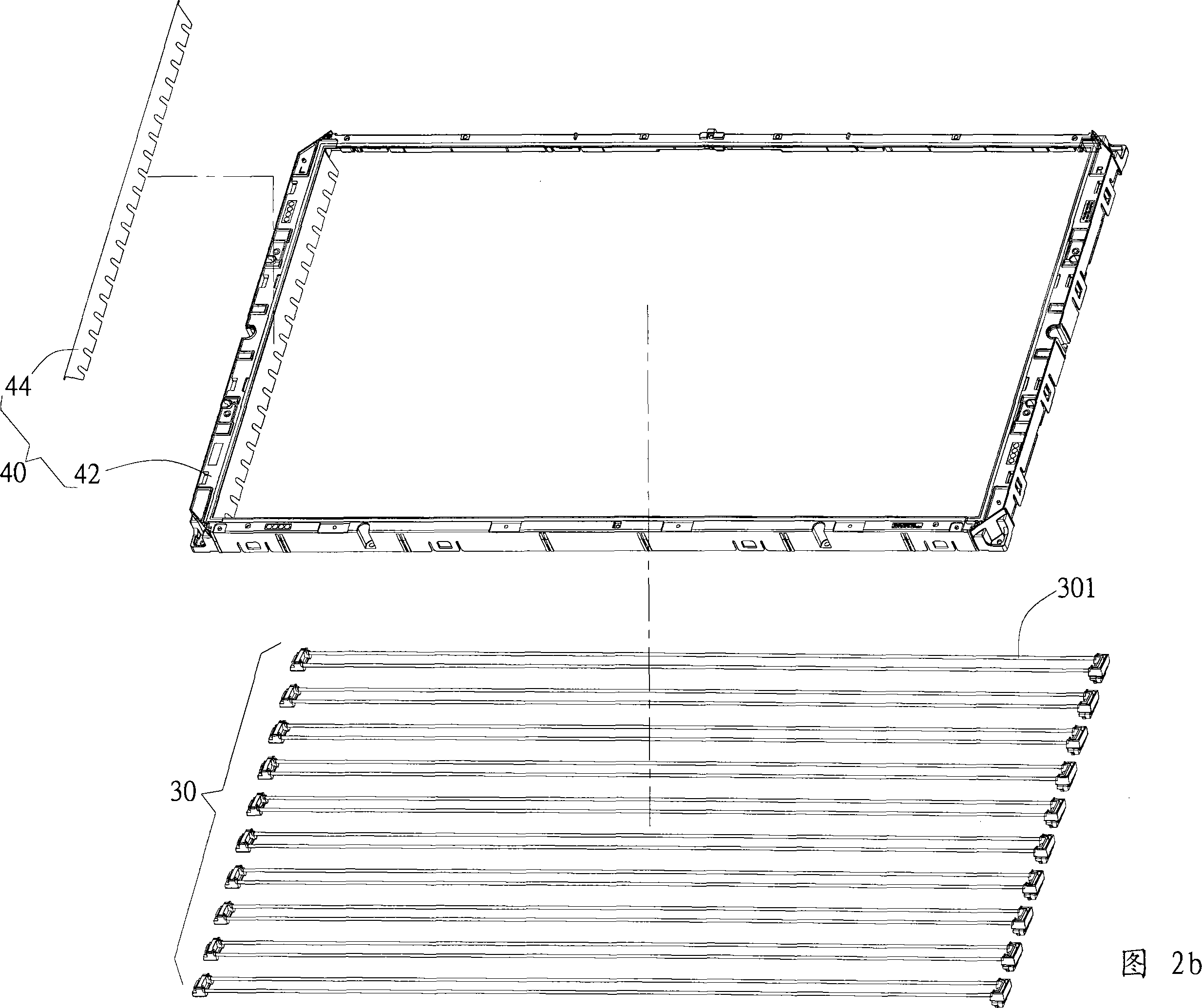
[0032] Fig. 2a is a schematic diagram showing the structure of a light source module according to an embodiment of the present invention. Figure 2b is an exploded view of Figure 2a. As shown in the figure, the light source module structure of this embodiment includes a light source module 30 and a lamp tube frame 40 . The lamp frame 40 includ...


PUM


Abstract

The invention discloses a light source module structure which includes a light source module and a lighting tube support. The light source module is mutually connected with the lighting tube support which contains a frame body and a reflector plate. The frame body of the lighting tube support is provided with a joint face which is provided with a plurality of welding concave parts, and the reflector plate is provided with a plurality of welding convex parts which are corresponding to the welding concave parts. The welding convex parts are taken as ultrasound weld lines and the welding concave parts are taken as ultrasound weld slots; the welding convex parts are heated and melted in the welding concave parts in an ultrasound mode so as to lead the welding convex parts and the welding concave parts to be mutually jointed and fixed.

Description

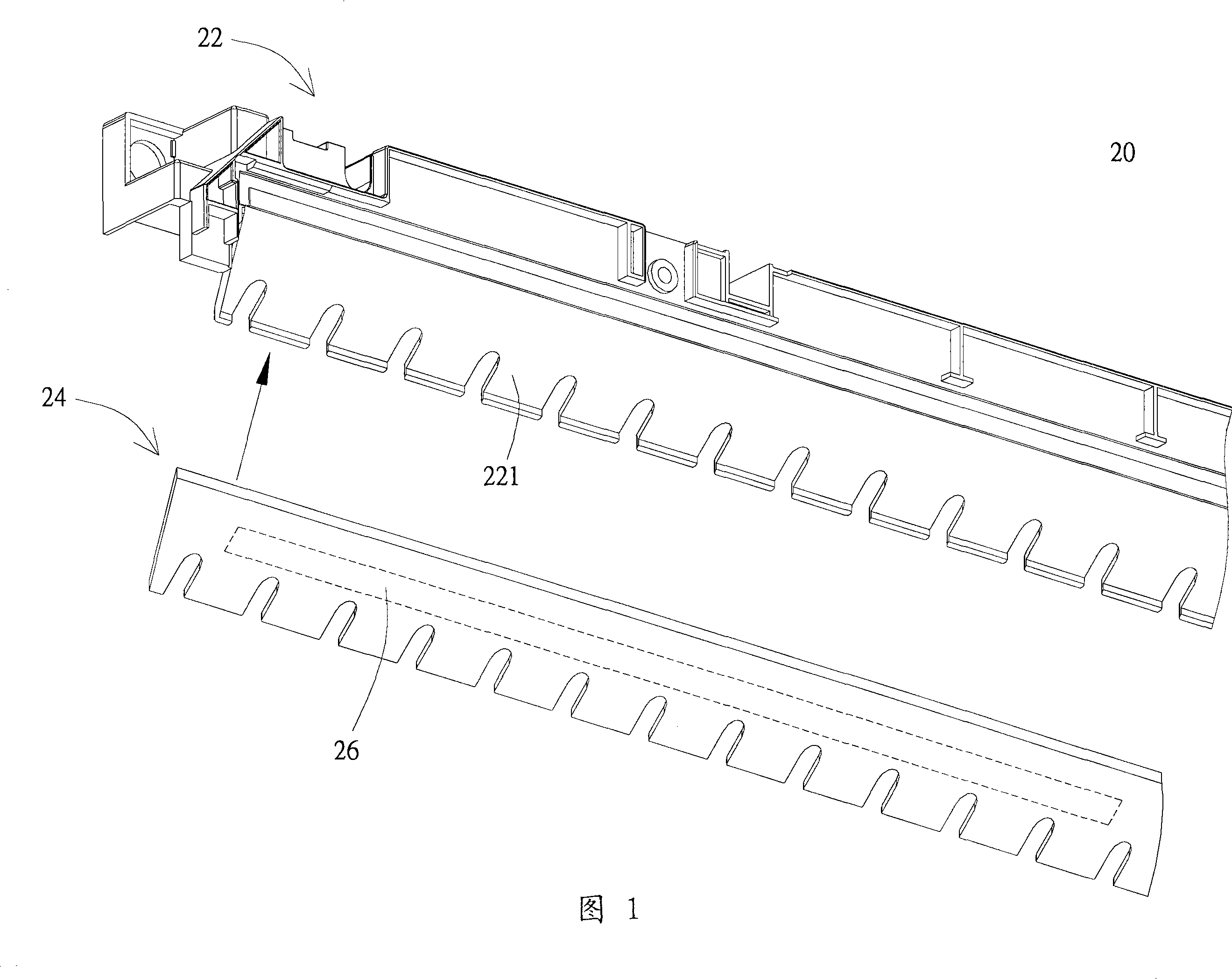
technical field [0001] The invention relates to a light source module structure; specifically, the invention relates to a lamp tube frame applied to the light source module structure. Background technique [0002] Display panels and display devices using thinner display panels have gradually become the mainstream of various display devices. For example, various panel displays, flat-screen TVs for home use, flat-panel monitors for personal computers and laptops, display screens for mobile phones and digital cameras, etc., are all electronic products that use a large number of thin display panels. One of the most important components in the display panel is the structure of the light source module. [0003] A traditional light source module structure includes a light source module and a lamp tube frame. FIG. 1 is a partial schematic diagram of a conventional lamp tube frame 20 . The lamp frame 20 includes a frame body 22 and a reflector 24 . The frame body 22 has a joint s...

Claims


Application Information

Patent Timeline
IPC IPC(8): F21V21/00F21V7/04F21V17/06G02F1/13357G02F1/1335
Inventor 陈唐博林继永萧登昆黄舜杰
Owner AU OPTRONICS CORP
Learn More