Electrical connection box

A technology for electrical connection boxes and connectors, which is applied in the directions of connections, circuits, and parts of connection devices, can solve the problems of increasing the number of parts and the troublesome operation of electronic control units installed on the main body.

Active Publication Date: 2008-07-16
YAZAKI CORP
View PDF1 Cites 11 Cited by
  • Summary
  • Abstract
  • Description
  • Claims
  • Application Information

AI Technical Summary

Problems solved by technology

However, in this case, there arises another problem of increasing the number of parts in addition to the troublesome operation of mounting the electronic control unit on the main body

Method used


Image

  • Electrical connection box
  • Electrical connection box
  • Electrical connection box

Examples


Embodiment Construction

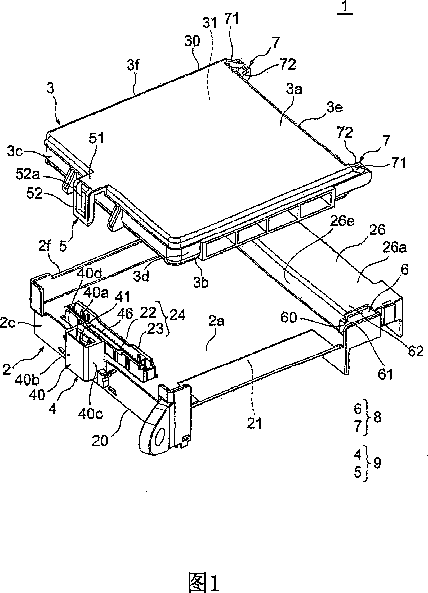
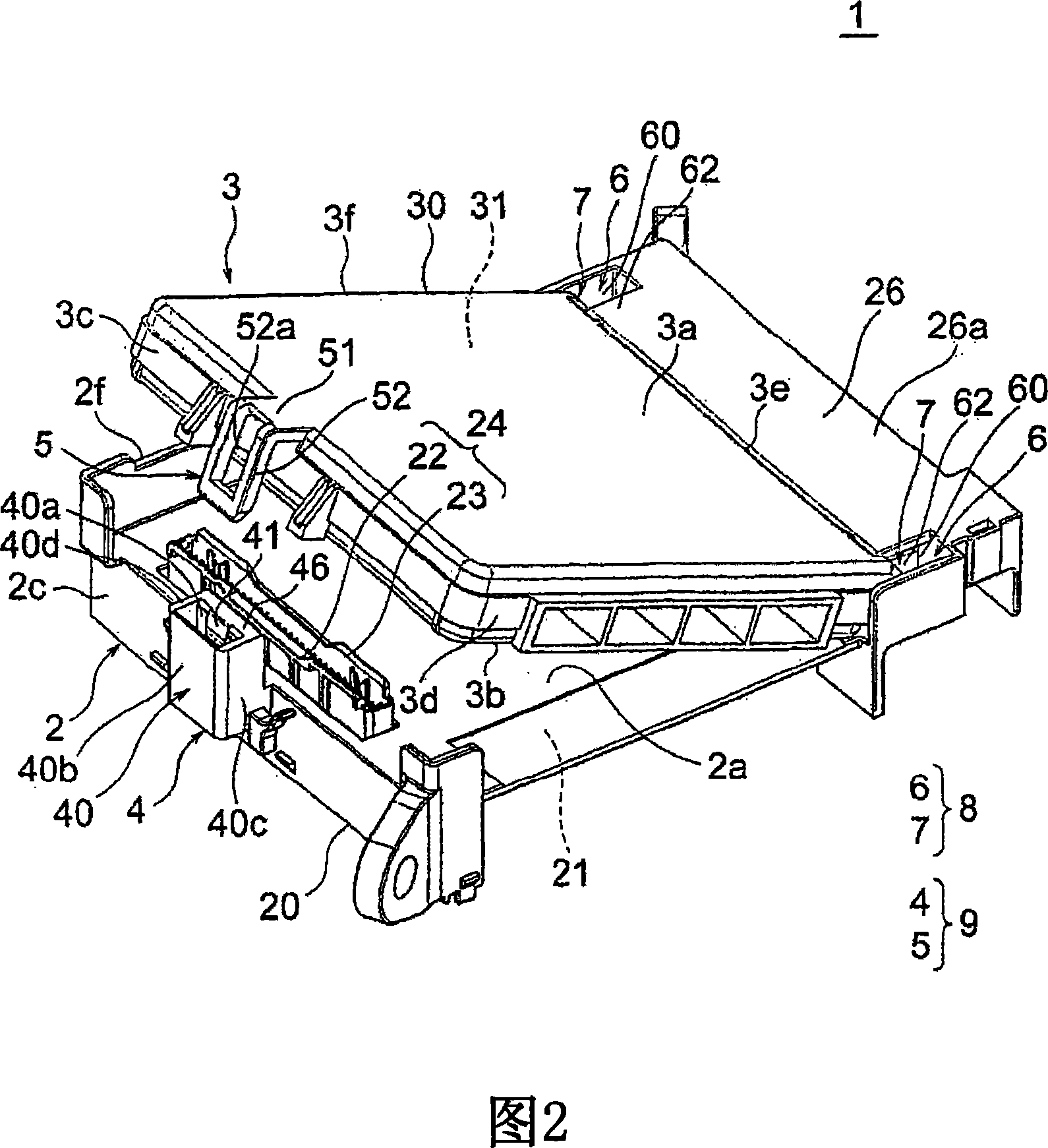
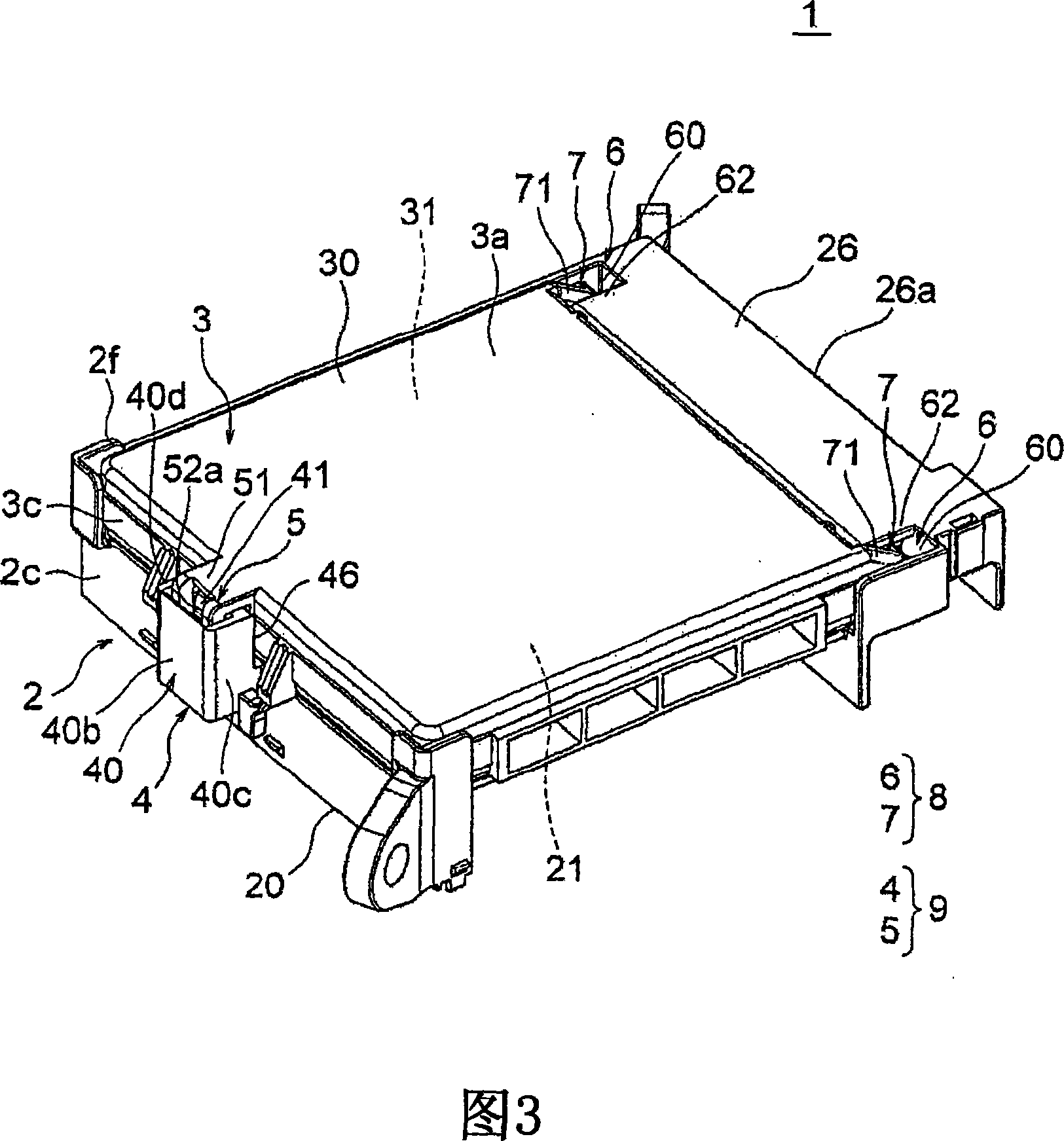
[0046] A preferred embodiment of the electrical junction box of the present invention will be described below with reference to FIGS. 1 to 9 . The electrical connection box 1 of this embodiment is fixed to a panel formed on a vehicle body or other parts of the vehicle, and various electronic devices mounted on the vehicle are electrically connected together in a predetermined pattern through the electrical connection box 1 .

[0047] As shown in FIGS. 1 to 4 , the electrical junction box 1 includes a main body 2, and an electronic control unit (hereinafter referred to as "ECU", which is an abbreviation for an engine control unit) 3 serving as a mounting part connected to the main body 2, A hinge 8 for rotatably and detachably connecting the main body 2 and the ECU 3 together, and a fixing portion 9 for fixing the main body 2 and the ECU 3 to each other.

[0048] The main body 2 includes a case 20 made of insulating synthetic resin and a printed circuit board 21 mounted on the ...


PUM


Abstract

An electrical connection box includes a main body, a mounting part connected to the main body, a lock arm provided on one of the main body and the mounting part, and a lock receiving part provided on the other of the main body and the mounting part. The lock arm includes an arm portion and a first engagement portion. The lock receiving portion includes a receiving portion having an insertion portion and a second engagement portion. The receiving portion includes a protrusion protruding from the surface of the receiving portion, the protrusion protruding farther than the second engagement portion protruding from the insertion portion so as to abut on the arm portion so that the lock arm is set at a predetermined position . A gap is formed between the receiving portion and the arm portion when the first engaging portion is engaged with the second engaging portion.

Description

technical field [0001] The present invention relates to an electrical connection box mounted on a vehicle or the like, and more particularly, to an electrical connection box in which a main body and a mounting member mounted on the main body are detachably connected together by a hinge. Background technique [0002] An electrical connection box (also referred to as a junction box) includes a main body including a case having a plurality of electronic devices (for example, fuses, relays, etc.) The electronic control unit has a control circuit for controlling the plurality of electronic devices. [0003] Generally, the above-mentioned electrical junction box is constructed such that an electronic control circuit is contained in a casing of the main body (see, for example, Patent Document 1). However, in recent years, in order to enhance the maintenance efficiency in the event of failure of the control circuit or the electronic control unit, and also to reduce the cost require...

Claims


Application Information

Patent Timeline
Patent Type & Authority Applications(China)
IPC IPC(8): H02G3/14
CPCH01R12/71H01R13/6271
Inventor 小澤圭介杉浦智宏久保田勝弘小林克和
Owner YAZAKI CORP
Why Eureka
Try Eureka