
Electromagnetic shielding optical window with double-layer circular ring metal gridding structure

A metal mesh grid, electromagnetic shielding technology, applied in the direction of magnetic field/electric field shielding, electrical components, etc., can solve the problem of high light transmittance and strong electromagnetic shielding efficiency can not be balanced, to overcome the concentrated distribution of high-order diffraction energy, improve imaging quality, the effect of improving shielding efficiency

Active Publication Date: 2008-07-16
HARBIN INST OF TECH
View PDF5 Cites 80 Cited by
  • Summary
  • Abstract
  • Description
  • Claims
  • Application Information

AI Technical Summary

Problems solved by technology

[0010] The purpose of the present invention is to overcome the shortcomings of the above-mentioned existing optical window electromagnetic shielding technical solutions, especially for the problem that the traditional single-layer grid metal grid cannot take into account the high light transmittance and strong electromagnetic shielding efficiency, and proposes a dual-layer The electromagnetic shielding optical window with a layered ring metal grid structure uses the different influence rules of the double-layer metal grid spacing on the light transmission performance and shielding performance to select the period and spacing of the grid to achieve basically constant light transmittance. In the case of the case, the shielding efficiency is greatly improved

Method used


Image

  • Electromagnetic shielding optical window with double-layer circular ring metal gridding structure
  • Electromagnetic shielding optical window with double-layer circular ring metal gridding structure
  • Electromagnetic shielding optical window with double-layer circular ring metal gridding structure

Examples


Embodiment Construction

[0032] Embodiments and accompanying drawings of the electromagnetic shielding optical window with a double-layer ring metal grid structure are described in detail as follows:

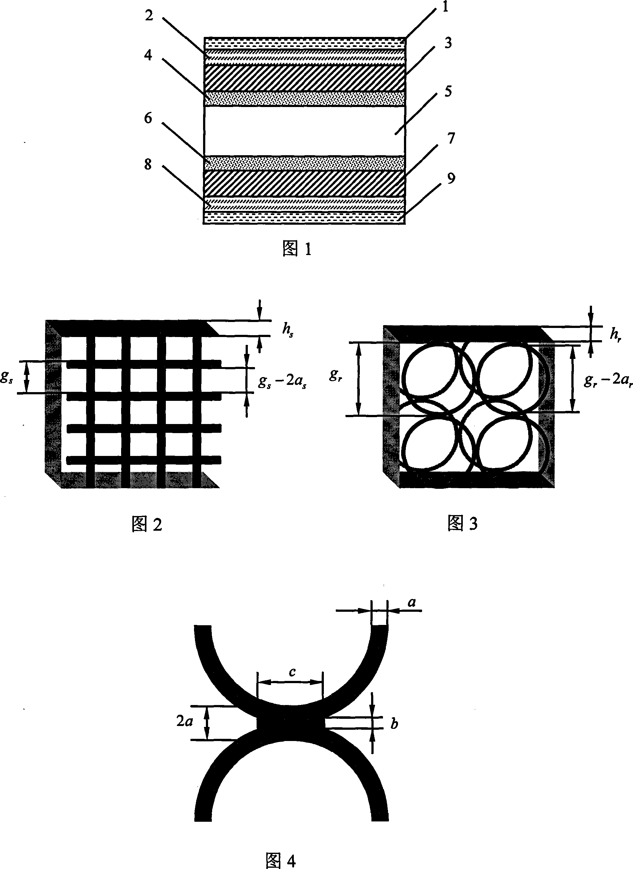
[0033]Accompanying drawing 1 is a schematic cross-sectional view of a typical preferred structure of an electromagnetic shielding optical window with a double-layer ring metal grid structure of the present invention. Among the figure 3 and 7 are single-layer ring metal grid structure layers respectively, and their structural parameters are identical, and are arranged in parallel; Among the figure 5 is the optical window transparent material substrate layer, and material can be any transparent material, as long as it can be used as It is a transparent optical window material that meets the requirements of the application, and can process the ring metal grid 3 and 7 on it according to a certain process flow; Bonding layer, 6 is the bonding layer that connects optical window substrate 5 and ring metal grid...


PUM

PropertyMeasurementUnit
Thicknessaaaaaaaaaa

Abstract

The invention relates an electromagnetic shielding optical window with a two-double cirque metal grating structure, which belongs to the optical transparent piece electromagnetic shielding technical field; the electromagnetic shielding optical window is formed by loading two layers of cirque metal gratings on two sides of the optical window; each layer of cirque metal grating is formed by closely connecting and distributing metal cirque units in a two-dimensional orthogonal arrangement mode; an outside diameter of a cirque of the two layers of cirque metal gratings is greater than pi / 2 times of a side length of a pane of the prior monolayer pane metal grating; the space between two layers of circular metal gratings is two to four times of the outside diameter of the cirque; compared with the prior monolayer pane metal grating, the optical window with the two-double circular metal grating does not reduce light transmittance, substantially improves shielding efficiency, homogenizes high-level energy diffracting distribution and solves the problems that the influences of high light transmittance, strong electromagnetic shielding efficiency and low imaging quality can not simultaneously considered in the prior optical window electromagnetic shielding technology.

Description

technical field [0001] The invention belongs to the field of electromagnetic shielding of optically transparent parts such as aerospace equipment, communication equipment and security facilities, and particularly relates to an electromagnetic shielding optical window with a double-layer ring metal grid structure. Background technique [0002] With the wide application of various electronic devices and the broadening and increasing intensity of electromagnetic wave application spectrum, higher and higher requirements are put forward for optical windows used in aerospace equipment and other fields. The concentrated expression is that optical windows are required to have high transparency While having little impact on imaging quality, it also has super strong broadband electromagnetic shielding ability. Especially in the field of aerospace equipment, the optical window of the aircraft is required to ensure high transparency to complete the detection or imaging task, and at the ...

Claims


Application Information

Patent Timeline
IPC IPC(8): H05K9/00
Inventor 谭久彬陆振刚
Owner HARBIN INST OF TECH
Learn More