Electromagnetic-shielding light window of double-layer interlaced multi-periodic metal ring nested array

A metal ring and electromagnetic shielding technology, applied in the direction of magnetic/electric field shielding, electrical components, etc., can solve the problems of low imaging quality impact, stray light distribution concentration, etc., to improve electromagnetic shielding effect, strong electromagnetic coupling, and improve electromagnetic shielding efficiency effect

Active Publication Date: 2015-07-29
HARBIN INST OF TECH
View PDF10 Cites 0 Cited by
  • Summary
  • Abstract
  • Description
  • Claims
  • Application Information

AI Technical Summary

Problems solved by technology

[0019] The purpose of the present invention is to overcome the deficiencies of the above-mentioned existing optical window electromagnetic shielding technical solutions, especially for the existence of advanced To solve the problem of relatively concentrated stray light distribution caused by sub-diffraction, an electromagnetic shielding light window with a double-layer interlaced multi-period metal ring nested array was developed to achieve the purpose of achieving depth homogenization of high-order diffraction and extremely low impact on imaging quality , but also has good electromagnetic shielding efficiency

Method used


Image

  • Electromagnetic-shielding light window of double-layer interlaced multi-periodic metal ring nested array
  • Electromagnetic-shielding light window of double-layer interlaced multi-periodic metal ring nested array
  • Electromagnetic-shielding light window of double-layer interlaced multi-periodic metal ring nested array

Examples


Embodiment Construction

[0059] The present invention is further described below with reference to accompanying drawing and preferred embodiment:

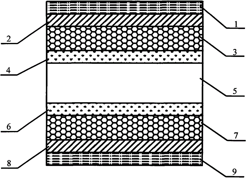
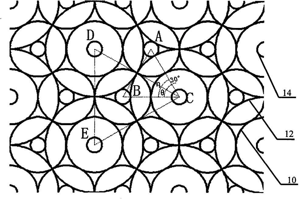
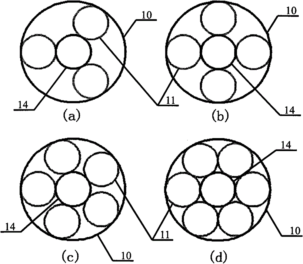
[0060] The electromagnetic shielding light window of the nested array of double-layer interlaced multi-period metal rings, two layers of metal grids 3 and 7 are placed in parallel on both sides of the transparent substrate of the light window or the substrate, and the two layers of metal grids 3 and 7 have the same The shape and structural parameters of the unit, the two layers of metal grids 3 and 7 are rotated and staggered, and each layer of metal grids is composed of a group of concentric metal ring pairs and another metal ring of different diameters arranged in an equilateral triangle. Cloth constitutes and cross-distributes on the transparent substrate of the light window or the surface of the substrate; wherein, the outer ring in the center of the concentric ring is used as the basic ring 10, and its interior contains a metal sub-ring 11 connected to...


PUM


Abstract

The invention discloses an electromagnetic shielding light window of a double-layer interlaced multi-cycle metal ring embedded array and belongs to the technical field of electromagnetic shielding. The electromagnetic shielding light window is formed by arranging two layers of metal grids in a rotating and interlaced mode and loading the two layers of metal grids on the two sides of a light window transparent substrate or a substratum. Each layer of metal grid is formed by densely arranging and connecting a set of concentric metal rings and another metal ring with the different diameter in an equilateral triangle mode, and the metal grids are distributed and loaded on the surface of the light window transparent substrate or the substratum in a crossed mode. The adjacent rings with the same diameter are communicated in an external tangent mode. The concentric rings are aligned with the external rings to serve as basic rings which are internally provided with metal sub rings communicated with the concentric rings in an internal tangent mode. Lines are overlapped at the joints where the rings are communicated in a tangent mode or metal which ensures reliable electric connection between the points of tangency of the metal rings is arranged at the joints where the rings are communicated, and therefore it is ensured that all the rings are mutually conducted. Through selection of interlaced angles of the double layers of grids, the structure of the metal grids of the electromagnetic shielding light window can effectively reduce non-uniformity of high-level diffraction light intensity distribution of the grids, and therefore stray light generated by diffraction can be distributed more evenly, and influences on imaging are less.

Description

technical field [0001] The invention belongs to the field of electromagnetic shielding of optically transparent parts, in particular to an electromagnetic shielding light window with a nested array of double-layer interlaced and multi-period metal rings. Background technique [0002] With the widening and increasing intensity of the electromagnetic wave application spectrum, the requirements for electromagnetic shielding light windows used in aerospace equipment, advanced optical instruments, communication equipment, medical diagnostic instruments and security facilities are getting higher and higher, mainly requiring light windows While having a super strong broadband electromagnetic shielding ability, it also has a very high light transmittance, and the less impact on optical imaging, observation, and detection, the better. For example, the optical window of an aircraft in the field of aerospace equipment must achieve high-quality isolation of electromagnetic signals insid...

Claims


Application Information

Patent Timeline
Patent Type & Authority Patents(China)
IPC IPC(8): H05K9/00
Inventor 陆振刚谭久彬林沈王赫岩
Owner HARBIN INST OF TECH
Why Eureka
Try Eureka