Electrical connector

a technology of electrical connectors and connectors, applied in the direction of coupling contact members, fixed connections, coupling device connections, etc., can solve the problems of increasing the cost of manufacturing and labor costs, increasing the problem of electromagnetic waves generated in the living environment, and requiring relatively high manufacturing costs and labor costs. , to achieve the effect of reducing labor requirements, improving the problem of emission, and enhancing electromagnetic shielding efficiency

Active Publication Date: 2021-07-13
PEGATRON
View PDF14 Cites 0 Cited by
  • Summary
  • Abstract
  • Description
  • Claims
  • Application Information

AI Technical Summary

Benefits of technology

[0006]The present invention provides a connector. The connector may enhance electromagnetic shielding efficiency to improve the problem of emission and interference of electromagnetic waves and may also reduce a labor requirement to cut down manufacturing costs.
[0008]Based on the above, the connector of the present invention is divided into the base, the transmission interface and the shielding cover. The base is soldered on the circuit board by using a surface mount (SMD) technology. The SMD technology replaces the conventional manual mounting through machine automatic mounting, to reduce manufacturing costs and enhance the product yield. Further, in the present invention, the shielding cover is used to accommodate and cover the base and the transmission interface, and the shielding layer is added onto the shielding cover, to block the electromagnetic waves of the transmission interface and restrict most of the electromagnetic waves to the accommodation space, thereby preventing the electromagnetic waves from being transmitted outwards and causing electromagnetic interference to other electronic devices.

Problems solved by technology

The accompanying disadvantage is that the living environment is filled with electromagnetic waves generated by the electronic products.
The interference between a wireless network base station and a third generation universal serial bus (USB 3.0) during signal transmission is more serious in a consumer product.
However, most of the existing electromagnetic shielding masks are made of metal (tinplate) and use a dual in line package (DIP) process, and this requires relatively high manufacturing costs and labor costs.
Consequently, some of the electromagnetic waves may be emitted from the apertures to the environment, affecting electromagnetic shielding efficiency.
In addition, the appearance of the existing electromagnetic shielding mask is also prone to the accumulation of static electricity, and finally leads to the problem of electrostatic discharge, causing the malfunction of a transmission signal.
This indicates that a grounding property of the existing electromagnetic shielding mask is insufficient.

Method used


Image

  • Electrical connector
  • Electrical connector
  • Electrical connector

Examples


Embodiment Construction

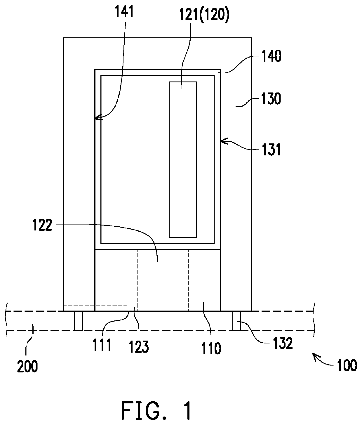
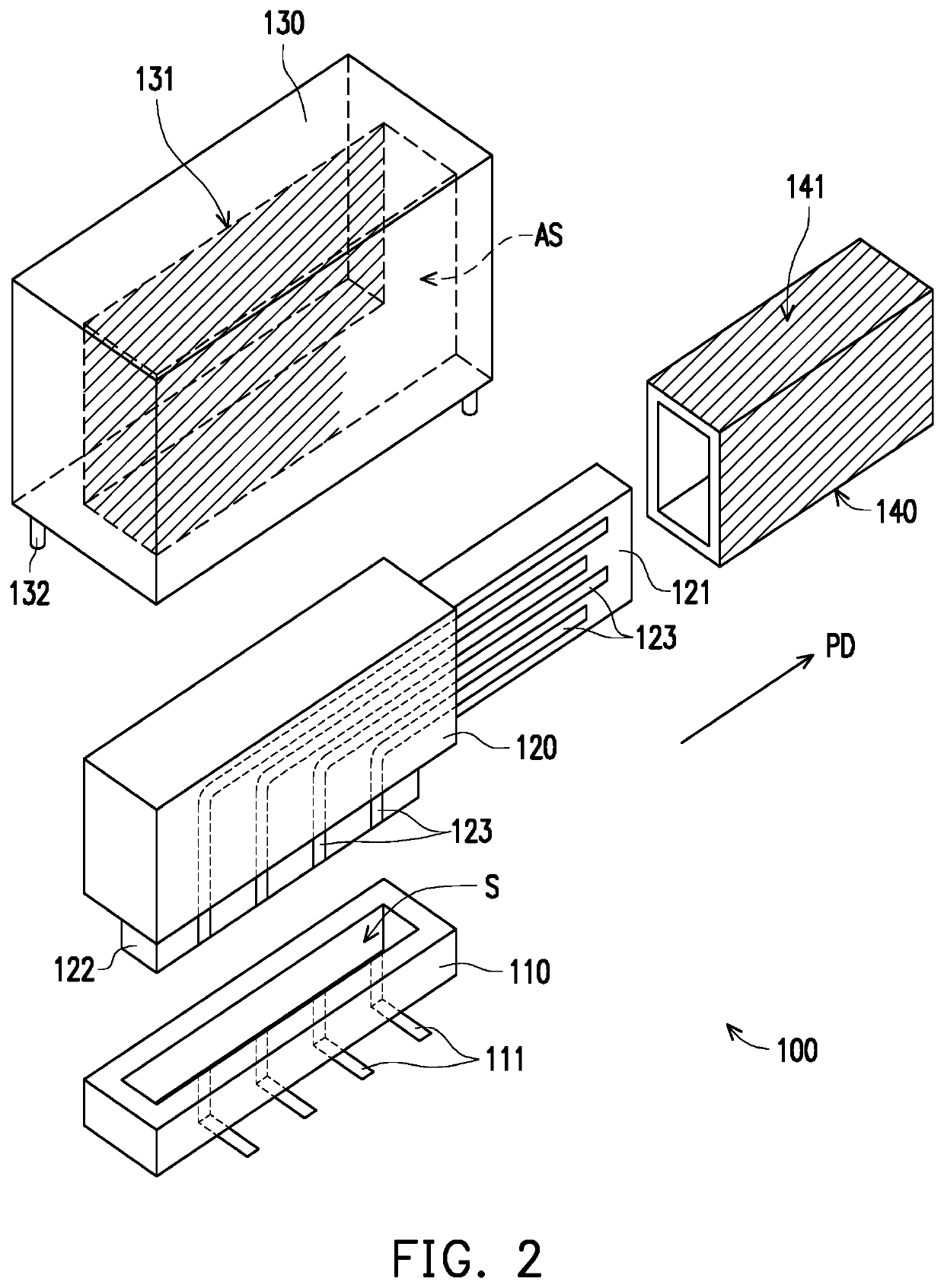
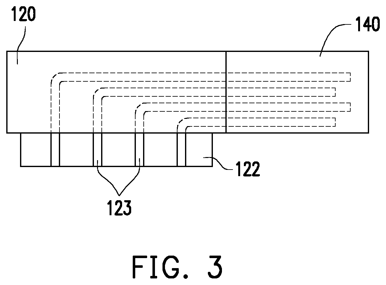
[0014]FIG. 1 is a schematic diagram of a connector according to an embodiment of the present invention. FIG. 2 is an exploded view of the connector in FIG. 1. FIG. 3 is a schematic diagram of a transmission interface in FIG. 2.

[0015]Referring to FIG. 1, in this embodiment, a connector 100 is adapted to be disposed on a circuit board. For example, the connector 100 is a third-generation universal serial bus (USB3.0 / 3.1) configured to connect to a corresponding connector or a thumb drive complying the same specification for supplying power or transmitting an electronic signal. In another embodiment, the connector may also be another type of bus, and is not limited to the third-generation universal serial bus (USB3.0 / 3.1). In addition, the bus is a standardized manner of exchanging data between computer components, that is, the bus provides data transmission and control logic for the components in a common manner.

[0016]Referring to FIG. 1 to FIG. 3, specifically, the connector 100 of t...


PUM


Abstract

A connector includes a base, a transmission interface, a shielding cover and a shielding layer. The base includes a slot. The transmission interface includes a clamping portion and a plugboard. The clamping portion is clamped in the slot and a portion of the plugboard protrudes out of the base. The shielding cover has an accommodation space and a shielding layer. The accommodation space is disposed to accommodate the base and the transmission interface, and the shielding layer is electroplated on an inner side surface of the shielding cover. The shielding cover covers the base and the transmission interface and is disposed to block electromagnetic waves generated by the transmission interface.

Description

CROSS-REFERENCE TO RELATED APPLICATION[0001]This application claims the priority benefit of Taiwan application serial no. 108101081, filed on Jan. 11, 2019. The entirety of the above-mentioned patent application is hereby incorporated by reference herein and made a part of this specification.BACKGROUNDTechnical Field[0002]The present invention relates to a connector, and in particular, to a connector capable of suppressing electromagnetic interference.Description of Related Art[0003]With the development of electronic technologies, various electronic products such as televisions, computers, smartphones and various communications devices have become increasingly popular. The accompanying disadvantage is that the living environment is filled with electromagnetic waves generated by the electronic products. Therefore, the electromagnetic interference and noise tolerance of the electronic products during data transmission have been gradually concerned by governments and enterprises.[0004]...

Claims


Application Information

Patent Timeline
Patent Type & Authority Patents(United States)
IPC IPC(8): H01R13/6581H01R12/70H01R13/648H01R13/03H01R12/57H01R13/6599
CPCH01R13/6581H01R12/707H01R13/035H01R13/6485H01R12/57H01R13/6599H01R12/712H01R13/5213H01R13/6594H01R24/60H01R13/648H01R2107/00
Inventor TSAO, WEI-CHUNCHEN, WEI-HSIN
Owner PEGATRON
Why Eureka
Try Eureka