Manufacturing device and method of polishing wheel

A manufacturing method and polishing wheel technology, applied in grinding/polishing equipment, metal processing equipment, manufacturing tools, etc., can solve the problems of polishing wheel imbalance, large vibration, low efficiency, etc., and achieve uniform spacing and simple and reasonable structure , high work efficiency

Inactive Publication Date: 2008-07-23
杨学海
View PDF0 Cites 0 Cited by
  • Summary
  • Abstract
  • Description
  • Claims
  • Application Information

AI Technical Summary

Problems solved by technology

[0002] The common polishing wheel is to overlap the multi-layer cloth, sisal or other plant fibers cut into pieces, and then sew it into a whole through thread, etc. This kind of sewing work is mostly manual, and its efficiency is very low. Ordinary sewing machines are used to sew, but the polishing wheels sewn by ordinary sewing machines, or the distance between the inner and outer suture lines of the polishing wheels cannot be kept consistent, resulting in imbalance and large vibration of the polishing wheels during use, thus Affect the polishing effect of the product; the internal and external strength of the product is inconsistent, and it is prone to damage during use, resulting in a relatively short life, or the center of the polishing wheel cannot be effectively stitched, resulting in the polishing wheel cannot be fully utilized, and the waste is relatively large

Method used


Image

  • Manufacturing device and method of polishing wheel
  • Manufacturing device and method of polishing wheel

Examples


Embodiment Construction

[0019] The present invention will be further described below in conjunction with the accompanying drawings and embodiments.

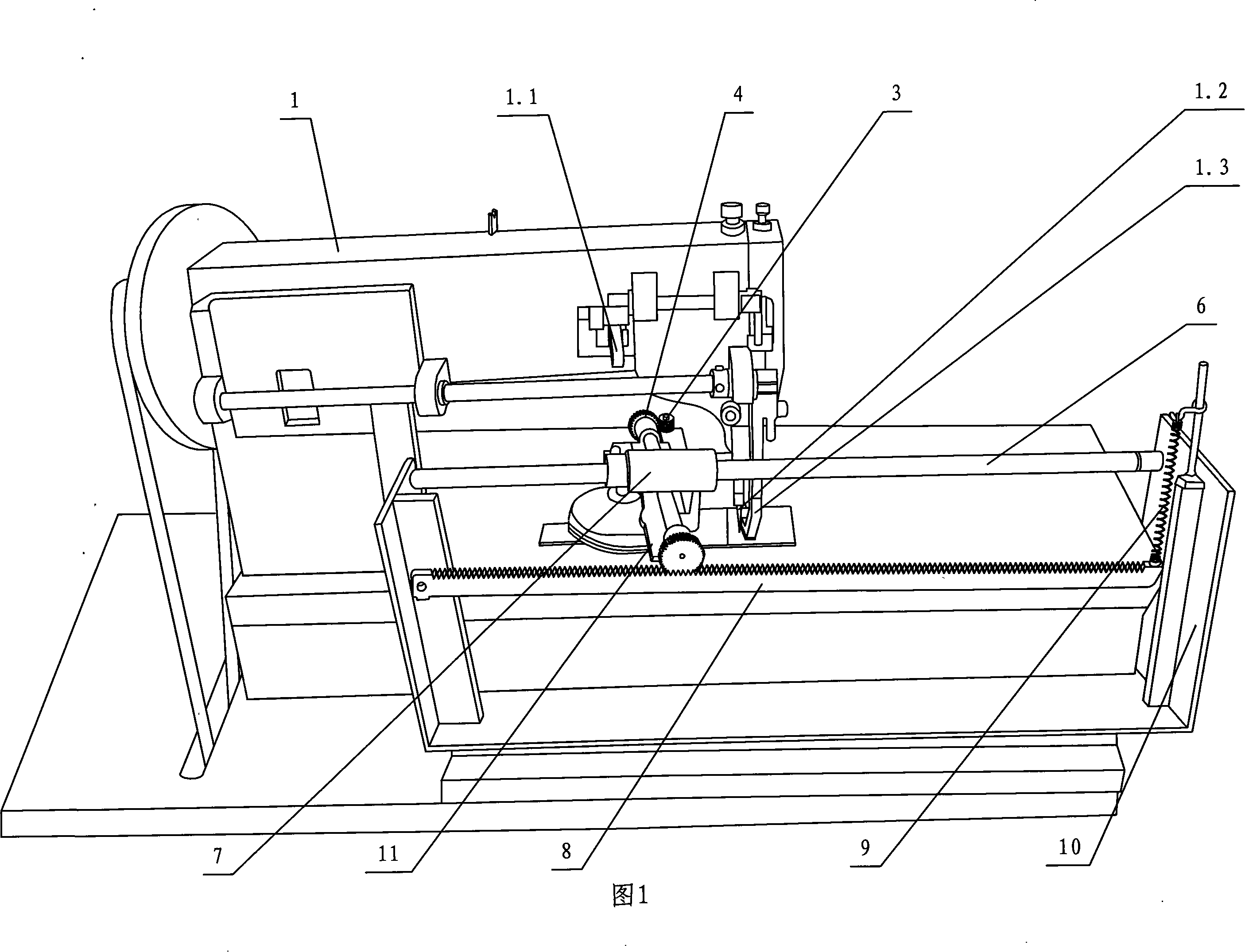
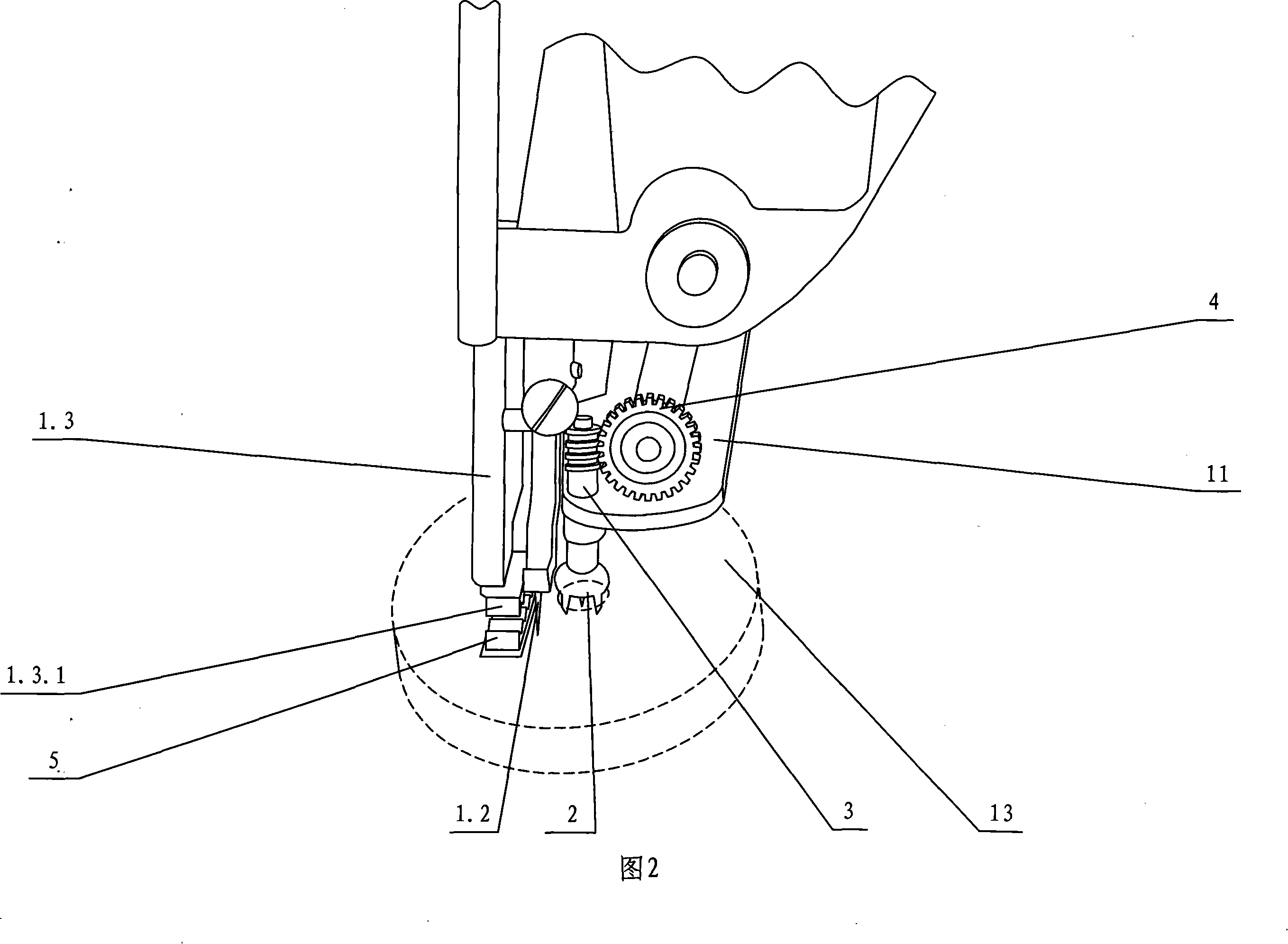
[0020] Referring to Fig. 1-Fig. 2, the manufacturing equipment of this buffing wheel comprises sewing machine 1 and buffing wheel driving mechanism, and this driving mechanism comprises claw 2, and its one end joins with the wheel core 13 center hole of buffing wheel, and the other end is connected with transmission One end of the rod 3 is connected, the other end of the transmission rod is meshed with one end of the worm wheel 4 through the worm, the other end of the worm wheel is meshed with the rack 8, the rack is set on the bracket 10, the bracket is set next to the sewing machine, and the transmission rod and the worm gear are respectively worn. On the mounting plate 11, the worm wheel 4 and the mounting plate 11 are crimped on the rack. The mounting plate 11 is connected to the guide rod 6 through the connecting sleeve 7 , and the guide rod is arr...


PUM


Abstract

The invention relates to a fabrication equipment and a fabrication method used for a polishing wheel. The fabrication equipment comprises a sewing machine and a polishing wheel driving mechanism; the driving mechanism comprises a claw; one end of the claw is connected with a small central hole of the wheel core of the polishing wheel and the other end thereof is connected with one end of a transmission rod; the other end of the transmission rod is engaged with one end of a worm wheel through a worm; a wheel tooth at the other end of the worm wheel is engaged with a rack; the rack is arranged on a bracket which is arranged beside the sewing machine. When being fabricated, a round basic sheet raw material is fabricated and a small central hole is opened at the same time; two layers and more basic sheets are overlapped together by taking the small central hole as the center; a thread involute with equal distances of an internal layer sewing line and an external layer sewing line is sewed on the basic sheet through the sewing machine so as to obtain the sewed polishing wheel; the small central hole is then taken as the center so as to punch a comparatively large assembly hole; finally, the periphery of the polishing wheel is cut and decorated by the punched assembly hole. The invention has the advantages of low fabrication cost and high working efficiency.

Description

technical field [0001] The invention relates to a manufacturing device and a manufacturing method of a polishing wheel. Background technique [0002] The common polishing wheel is to overlap the multi-layer cloth, sisal or other plant fibers cut into pieces, and then sew it into a whole through thread, etc. This kind of sewing work is mostly manual, and its efficiency is very low. Ordinary sewing machines are used to sew, but the polishing wheels sewn by ordinary sewing machines, or the distance between the inner and outer suture lines of the polishing wheels cannot be kept consistent, resulting in imbalance and large vibration of the polishing wheels during use, thus Affect the polishing effect of the product; the internal and external strength of the product is inconsistent, and it is prone to damage during use, resulting in a relatively short life, or the center of the polishing wheel cannot be effectively stitched, resulting in the polishing wheel cannot be fully utilize...

Claims


Application Information

Patent Timeline
IPC IPC(8): B24D18/00
Inventor 杨学海
Owner 杨学海
Why Eureka
Try Eureka