

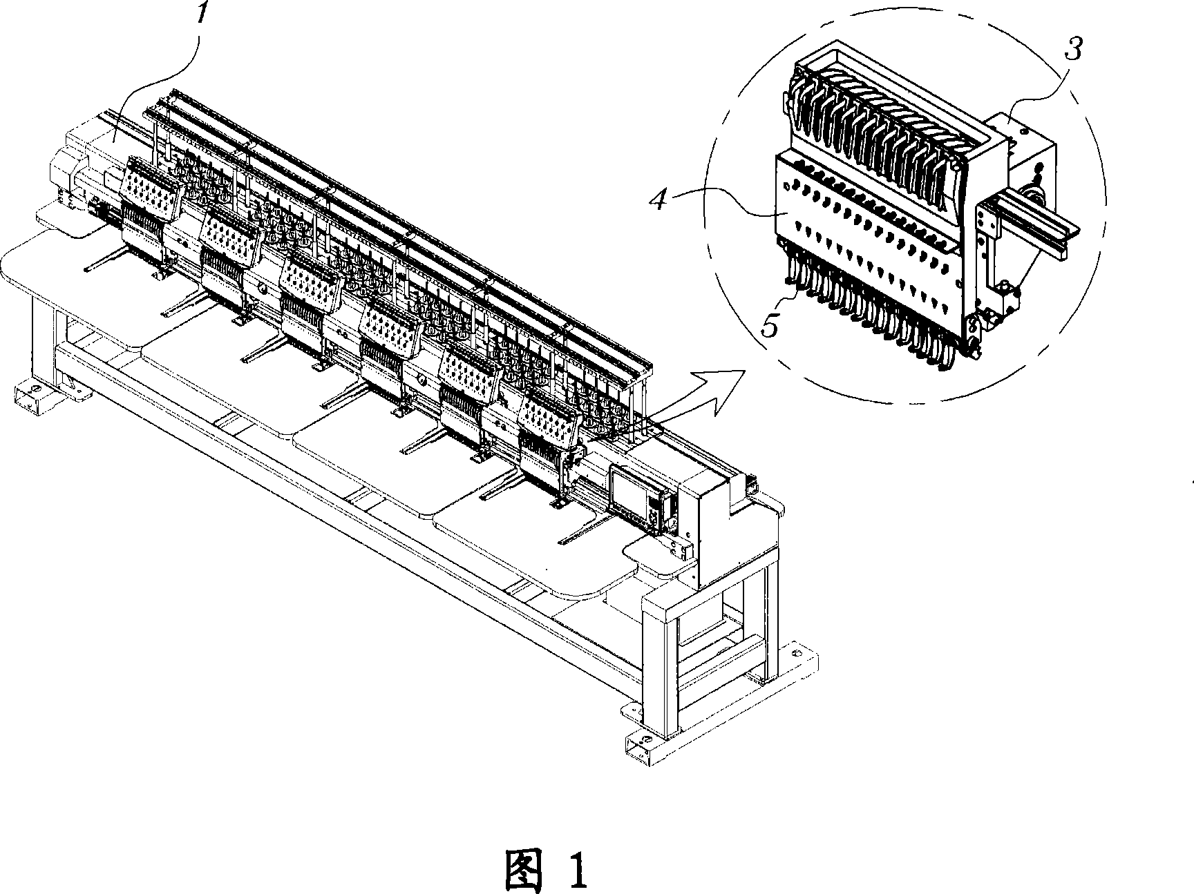
Device for lifting presser foot of embroidering machine
A presser foot and presser foot height technology, applied to the mechanism of embroidery machines, embroidery machines, feeding devices, etc., can solve the problem of difficult adjustment of the height of the presser foot 5
- Summary
- Abstract
- Description
- Claims
- Application Information
AI Technical Summary
Problems solved by technology
Method used
Image

Examples
Embodiment Construction
[0030] The presser foot lifting device of the embroidery machine according to the exemplary embodiment of the present invention will be described more fully below with reference to the accompanying drawings. Wherever necessary, the same reference numbers will be used throughout the drawings and description to refer to the same or like parts.
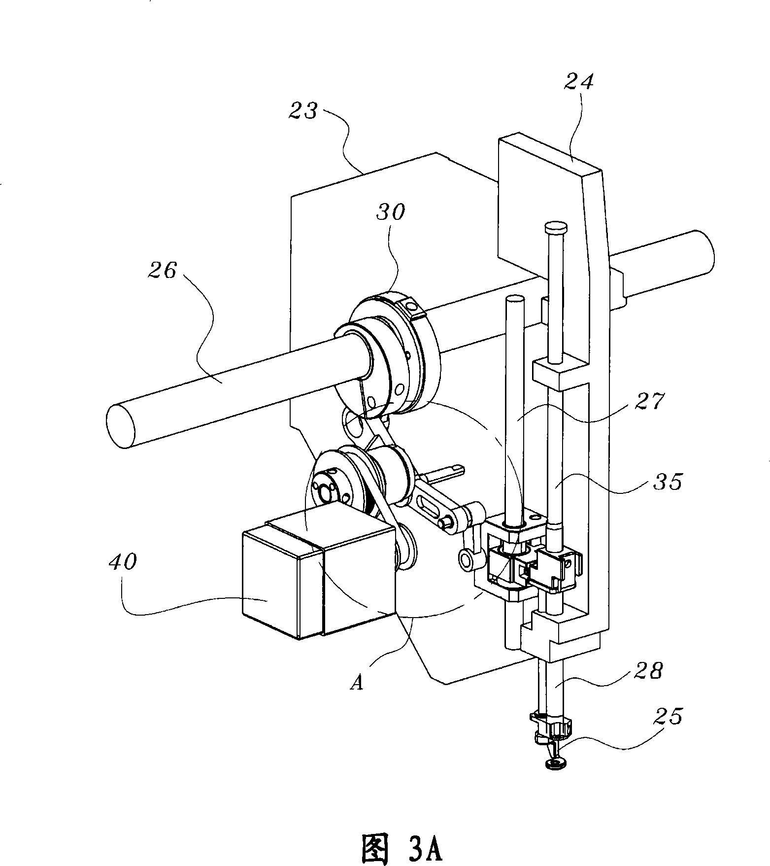
[0031] 3A is a perspective view illustrating an installation state of a presser foot lifting device of an embroidery machine according to an exemplary embodiment of the present invention, and FIG. 3B is an enlarged view illustrating a portion 'A' in FIG. 3A . 4 is an exploded perspective view illustrating a presser foot lifting device of an embroidery machine according to an exemplary embodiment of the present invention.
[0032] In addition, FIG. 5A is a partial perspective view illustrating an installation state of a presser foot lifting device of an embroidery machine according to an exemplary embodiment of the present invention, and ...
PUM
 Abstract
Description
Claims
Application Information