Variable spiracula lifting device

A valve lift and valve technology, which is applied to valve devices, engine components, machines/engines, etc., can solve problems such as cost and packaging energy balance, and achieve the effects of simple structure, reduced fuel consumption, and convenient control

Inactive Publication Date: 2008-07-23
许小法
View PDF0 Cites 14 Cited by
  • Summary
  • Abstract
  • Description
  • Claims
  • Application Information

AI Technical Summary

Problems solved by technology

Electrohydraulic and electromagnetic valve control systems do have the potential to allow throttleless engines, however, these systems are strictly prototype systems and there are substantial cost, packaging, and energy balance challenges before they can be produced need to overcome

Method used


Image

  • Variable spiracula lifting device
  • Variable spiracula lifting device
  • Variable spiracula lifting device

Examples


Embodiment 1

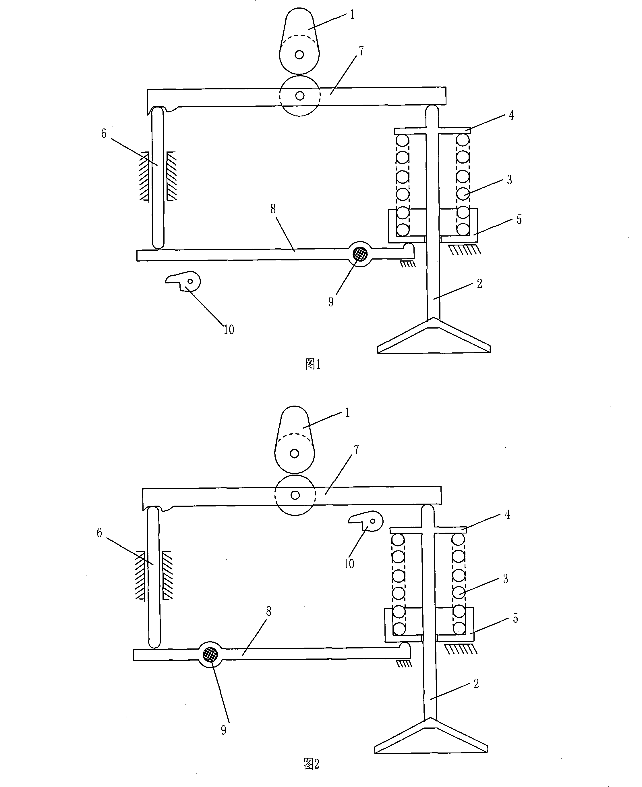
[0016] Embodiment 1: As shown in Fig. 1 , it is a schematic structural diagram of Embodiment 1 of the present invention. The variable valve lift device in this embodiment includes a valve 2, a valve spring 3 and a cam 1. The valve 2 is installed in the air passage of the cylinder head and is used to control the opening and closing of the air passage. The cam 1 is located above the valve 2 and is used to drive the valve 2 to move up and down. Valve 2 overcoats a valve spring 3, and the upper end of the valve 2 is fixedly connected with a spring upper seat 4, which can compress the valve spring 3. At the lower end of the valve spring 3, a seat under the spring is provided with a very cup 5, and the seat under the spring is very cup 5 and is positioned on the cylinder head.

[0017] Compared with the existing variable valve lift device, the improvement of this embodiment is mainly that a lever mechanism is added. Under the normal rotation of the cam 1, the mechanism can transfer...

Embodiment 2

[0021] Embodiment two: as shown in accompanying drawing 2. The scheme disclosed in this embodiment is similar to the scheme disclosed in Embodiment 1. In this scheme, the control cam wheel 10 is changed from controlling the lower lever 8 to controlling the upper lever 7. At the same time, the cam 1 and the upper lever 7 contact the force point and the upper lever. 7 and valve 2 distances are less than lower lever shaft 9 and lower lever 8 and spring seat tappet 5 contact point distances. The positions and connections of other components are consistent with those in Embodiment 1.

[0022] Contrary to Embodiment 1, when the valve 2 is required to move to the maximum extent with the rotation of the cam 1, firstly the control cam wheel 10 needs to be rotated until there is a distance between its upper edge and the upper lever 7, when the cam 1 rotates and pushes the upper lever 7 to act , the upper lever 7 is directly tilted to the right, thereby pressing down the valve 2, and th...

Embodiment 3

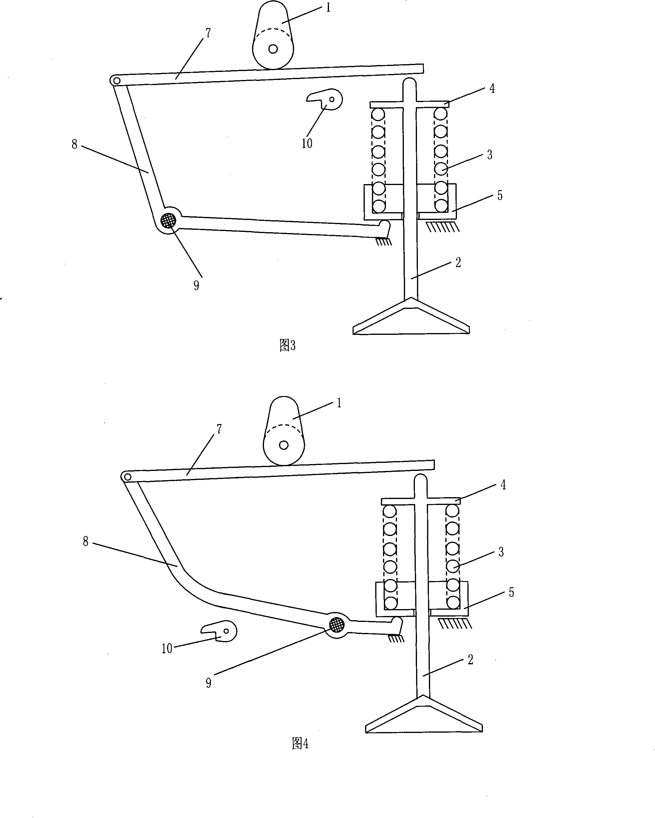
[0023] Embodiment three: as shown in accompanying drawing 3. This embodiment is consistent with the second embodiment in terms of structure and principle, and is a simplification of the second embodiment. The connecting transmission rod 6 in the second embodiment is canceled, and the upper lever 7 and the lower lever 8 are directly connected together through hinges. The transmission of power is realized through the hinge between the upper lever 7 and the lower lever 8 . The control and working process of this embodiment are consistent with the second embodiment, and will not be repeated here.


PUM


Abstract

The invention relates to a lift device for variable valves, comprising a valve arranged in the air passage of cylinder cover, a cam rotated synchronously with the engine crankshaft and a valve spring sleeved on the valve, which is characterized in that an upper seat of the spring is arranged on the upper end of the valve spring; the upper seat of the spring is fixedly connected with the valve; the lower end of the valve spring is arranged in the cylinder cover through the lower seat cup of the spring; a lever mechanism for controlling the valve action conveniently is connected between the cam and the valve. The lift device for variable valves has the advantages that the purpose of controlling valve action can be reached by adding a lever mechanism, the device is simple in structure and convenient in control, can reduce the pumping loss and the fuel oil consumption of engine.

Description

technical field [0001] The invention belongs to the field of engine manufacture, in particular to a variable valve lift device. Background technique [0002] The engine valves are in most cases opened and closed under a fixed cam drive, and the resulting valve action is a compromise between the high engine speed and the engine valve action time requirements at low engine speeds. In the original structure, there are disadvantages of large pumping loss and large fuel loss. More recently, devices to adjust timing determined by fixed driven camshafts have been produced that enhance engine performance. These devices are as simple as cam variable phasing devices, which control the angular position of the cam relative to the cam drive sprocket and the cam lobe switch. [0003] These variable cam timing systems provide significantly enhanced engine output over a wide range of engine speeds compared to fixed timing naturally aspirated engines, and can functionally replace part-thro...

Claims


Application Information

Patent Timeline
Patent Type & Authority Applications(China)
IPC IPC(8): F01L13/00
Inventor 许小法
Owner 许小法
Why Eureka
Try Eureka