
Backlight module and fixing structure thereof

A technology for fixing structures and backlight modules, which is applied in optics, nonlinear optics, lighting devices, etc., and can solve problems such as warping of optical sheets, inability to completely fix optical sheets, and glow lines on display panels

Active Publication Date: 2008-07-23
AU OPTRONICS (SUZHOU) CORP LTD +1
View PDF0 Cites 10 Cited by
  • Summary
  • Abstract
  • Description
  • Claims
  • Application Information

AI Technical Summary

Problems solved by technology

Since the traditional method of fixing the optical sheet is only to use the frame to buckle or clamp the optical sheet, it is impossible to completely fix the optical sheet
Also, the frame only partially touches the optics and cannot fully fit the optics
Therefore, when the backlight module is impacted, the optical sheet and the frame collide with each other, causing the optical sheet to warp, causing light leakage from the backlight module or glow lines on the LCD panel, and even causing the optical sheet to break

Method used


Image

  • Backlight module and fixing structure thereof
  • Backlight module and fixing structure thereof

Examples


Embodiment Construction

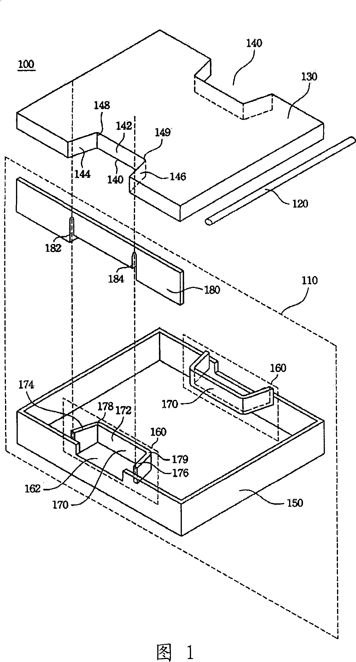
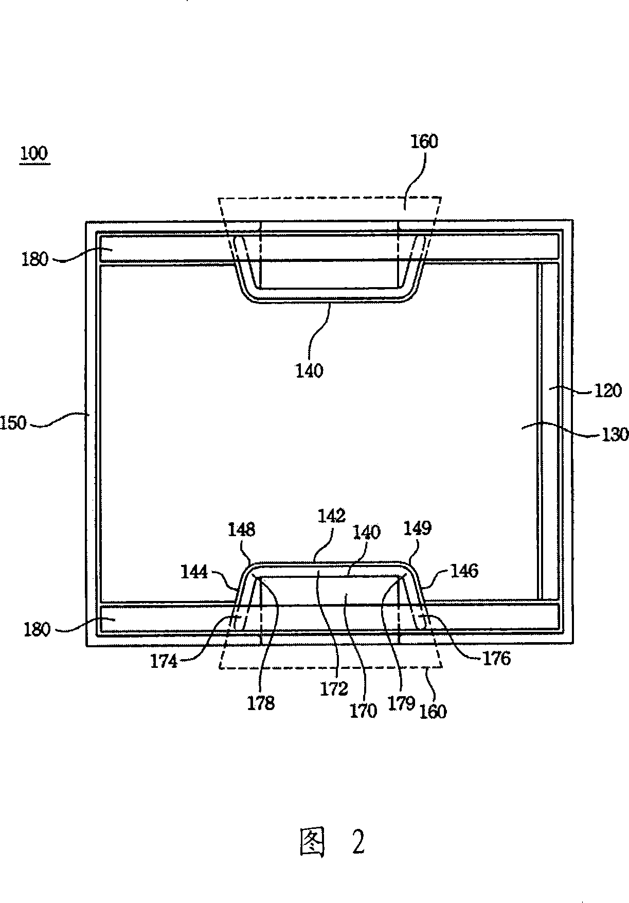
[0024] Please refer to FIG. 1 and FIG. 2 , which respectively illustrate an exploded view and a top view of a backlight module 100 according to an embodiment of the present invention. The backlight module 100 is used to supply uniform light to the liquid crystal display panel, and includes a light source 120 , a light guide plate 130 and a fixing structure 110 . The function of the light guide plate 130 is to guide the light from the light source 120 so that the light is evenly transmitted to the liquid crystal display panel. There is a groove 140 on the side of the light guide plate 130 , which cooperates with the fixing structure 110 to fix the light guide plate 130 .

[0025] The fixing structure 110 includes a frame 150 for accommodating the light guide plate 130 and the light source 120 . The frame 150 is connected to the positioning structure 160 and can engage the groove 140 so that the light guide plate 130 is fixed in the frame 150 , thereby fixing the position of th...


PUM


Abstract

The invention discloses a backlight module and a relative fixing structure, wherein the fixing structure is used to fix a light guide plate of the backlight module, the fixing structure is provided with a frame to contain the light guide plate, a positioning structure is connected with the frame to mesh the groove on the side face of the light guide plate to fix the light guide plate, the bottom baffle of the positioning structure is contacted with the bottom of the groove, two sides of the bottom baffle are respectively connected with one side baffle couple respectively bent and contacted with two side faces of the groove.

Description

technical field [0001] The invention relates to a backlight module of a liquid crystal display, and in particular to a fixing structure for fixing an optical sheet of the backlight module. Background technique [0002] The backlight module is one of the key components of the liquid crystal display panel. In view of the fact that the liquid crystal itself does not emit light, a backlight module is needed to supply light so that the liquid crystal panel can provide normal images with uniform brightness. There are multiple optical sheets in the backlight module, such as a light guide plate, a diffusion sheet and a prism sheet, which are used to evenly distribute the light emitted by the light source on the liquid crystal panel, thereby improving the brightness of the liquid crystal panel. [0003] The assembly and manufacturing process of the backlight module is a process of combining the frame, the backlight and various optical sheets, such as light guide plates and diffusion...

Claims


Application Information

Patent Timeline
IPC IPC(8): G02F1/13357G02F1/1333F21V21/00G02F1/1335
Inventor 陈杰周如磊
Owner AU OPTRONICS (SUZHOU) CORP LTD
Learn More