Apparatus and method for measuring optical system parameter

A technology of measuring device and optical system, which is applied in the direction of measuring device, adopting optical device, exposure device of photographic plate-making process, etc., can solve problems such as inability to measure, achieve error elimination, high measurement accuracy, and improve the effect of eccentricity measurement accuracy

Active Publication Date: 2008-07-23
SHANGHAI MICRO ELECTRONICS EQUIP (GRP) CO LTD
View PDF0 Cites 57 Cited by
  • Summary
  • Abstract
  • Description
  • Claims
  • Application Information

AI Technical Summary

Problems solved by technology

This method sometimes requires contact measurements wi...

Method used


Image

  • Apparatus and method for measuring optical system parameter
  • Apparatus and method for measuring optical system parameter

Examples


Embodiment approach

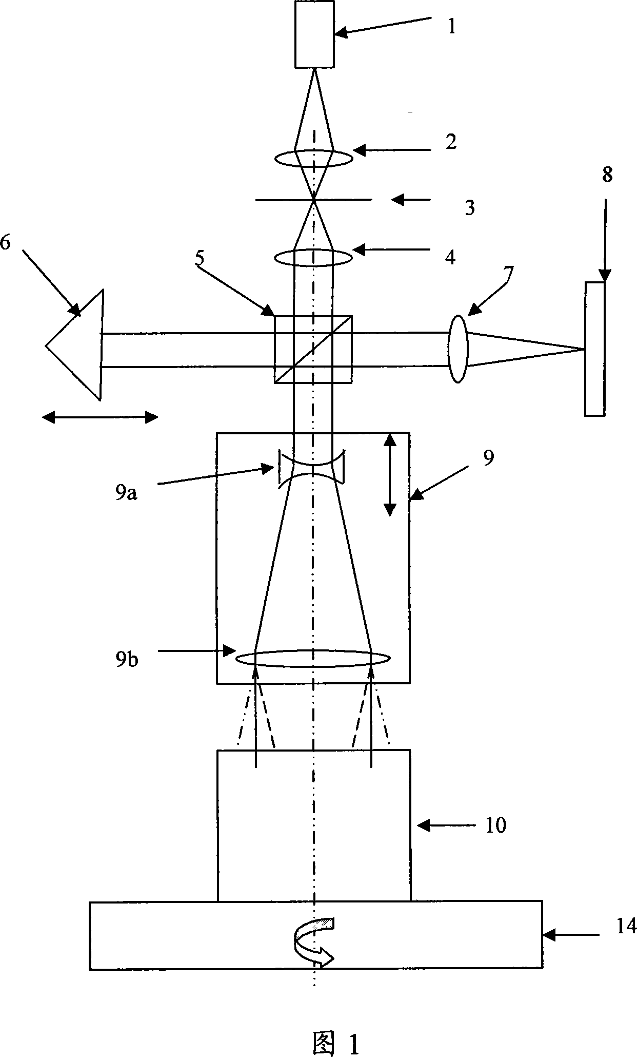
[0054] As shown in Figure 1, the present invention provides a kind of measuring device for measuring optical system parameters, comprising:

[0055] Light source 1, described light source 1 is short-coherent light source, usually adopts short coherence length light-emitting diode (LED), and it has good spatial coherence and poor time coherence shape, and coherence length is about 20um;

[0056] The focusing mirror 2 is located under the light source 1;

[0057] The pinhole 3 is located at the lower focal length of the focusing mirror 2;

[0058] The collimating lens 4 is located below the pinhole 3, and the collimating lens has a good ability to eliminate spherical aberration;

[0059] The beam splitter 5 is located below the collimating lens 4;

[0060] The one-dimensional mobile stage (not shown in the figure) is horizontally arranged on one side of the beam splitter 5, and is jointly composed of mechanical coarse displacement and PZT (piezoelectric ceramics) fine displace...


PUM


Abstract

A parameter measurement device of optical system comprises a short coherent light module, a focusing lens, a collimation lens, a filtering pinhole, a splitter, a corner reflector, an one-dimension accurate mobile station, an adjustable focus telescope, a micro swivel, a focusing lens and an imaging CCD. And a relative measurement method uses optical interferometry to accurately measure the eccentricity, inclination, lens thickness and lens distances of an object optical system. The invention can improve the eccentricity measurement accuracy of lens to match higher eccentricity demand, realize the final measurement of internal distances in optical system and realize the distance of assembled optical system.

Description

technical field [0001] The invention relates to a measuring device for measuring parameters of an optical system and a measuring method thereof, in particular to centering and spacing detection used in the assembling process of a lithography objective lens in lithography projection. Background technique [0002] In recent years, in the field of semiconductor lithography, the projection lithography technology has been continuously improved, and the lines have been advanced in a finer direction. At present, the critical size of the chip has reached the lithography resolution capability of 45nm. The imaging quality of the optical projection objective in the lithography system is a key factor affecting the resolution of the lithography. The centering of the lithography objective during the adjustment process and the thickness between different optical lenses will greatly affect the final optical quality of the objective. Quality, which requires sophisticated on-line measurement ...

Claims


Application Information

Patent Timeline
IPC IPC(8): G03F7/20G01B11/27G01B11/14
Inventor 刘国淦蔡燕民
Owner SHANGHAI MICRO ELECTRONICS EQUIP (GRP) CO LTD
Why Eureka
Try Eureka