Blade tip gap measuring device, system and method based on endoscope and linear structured light
A technology of blade tip clearance and measuring device, which is applied to measuring devices, optical devices, instruments, etc., can solve the problems of poor measurement accessibility, high measurement accuracy requirements, and low operability, so as to meet the requirements of the measurement environment, The effect of reducing radial complexity
- Summary
- Abstract
- Description
- Claims
- Application Information
AI Technical Summary
Problems solved by technology
Method used
Image
Examples
specific Embodiment approach 1
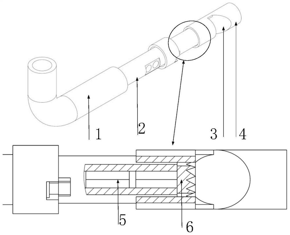
[0043] Specific implementation mode 1. Combination figure 1 In this embodiment, the tip clearance measurement device based on the endoscope and the line structured light is used to realize the online measurement of the tip clearance of the aeroengine in the assembled state. The device includes a mounting tube 1, a side-view endoscope 2, a reflector 3, a reflector fixing device 4, a point light source emitter 5 and a wave lens 6;
[0044] The installation pipe 1 is used to install and position the tip clearance measuring device through the endoscope hole on the engine;
[0045] The side-viewing endoscope 2 is a cylinder as a whole, fixed on one end of the installation tube 1, and two openings are provided on the side to install a camera and an illumination device respectively; they are used for shooting and providing ambient light.
[0046] The point light source emitter 5 and the wave lens 6 form a line-structured light emitting device, and the light beam emitted by the point...
specific Embodiment approach 2
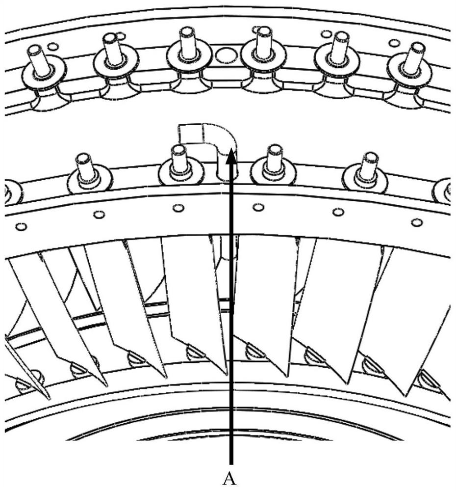
[0049] Specific embodiment two, combine Figure 2 to Figure 5 Describe this embodiment. This embodiment is the measurement system of the blade tip clearance measurement device based on the endoscope and line structured light described in the first embodiment, including the blade tip clearance measurement device described in the first embodiment, facing the endoscope The joint calibration module of mirror and line structured light measurement and the identification and calculation module of the sharp gap between leaves;
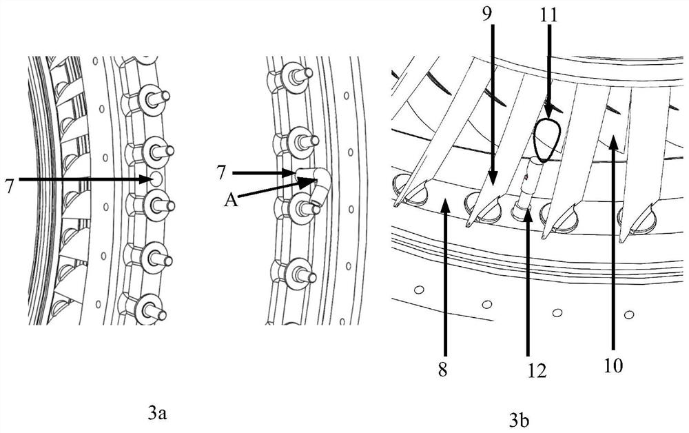
[0050] image 3 a is a schematic diagram of the engine endoscope hole (taking CFM56 as an example), using the existing endoscope hole 7 on the stator blade of the engine for measurement, the engine blade tip can be inspected without changing the engine design or destroying the engine structure. Gaps are measured.
[0051] image 3 In b: casing inner wall 8 , stator blade 9 , rotor blade 10 , the measurement area is the blade tip clearance area 11 , and the ...
specific Embodiment approach 3
[0063] Specific embodiment three, combine Figure 5 This embodiment is described. This embodiment is the measurement method of the blade tip clearance measurement system based on the endoscope and line structured light described in the second embodiment. The method is realized by the following steps:
[0064] S1: Install the blade tip clearance measurement device to the specified position inside the engine, ensure that the clearance position is within the working distance of the device, and try to ensure that the line structured light plane passes through the engine rotation axis.
[0065] S2: Collect the tip clearance image, and record the position of the engine rotation.
[0066] S3: Identify the line laser stripes formed where the line structured light irradiates the position of the blade tip gap.
[0067] S4: Judging whether there are two discontinuous line segments forming a certain angle with each other (an obtuse angle between 90-180 degrees), if it cannot be detected,...
PUM
 Abstract
Description
Claims
Application Information
 - R&D
- Intellectual Property
- Life Sciences
- Materials
- Tech Scout
- Unparalleled Data Quality
- Higher Quality Content
- 60% Fewer Hallucinations
Browse by: Latest US Patents, China's latest patents, Technical Efficacy Thesaurus, Application Domain, Technology Topic, Popular Technical Reports.
© 2025 PatSnap. All rights reserved.Legal|Privacy policy|Modern Slavery Act Transparency Statement|Sitemap|About US| Contact US: help@patsnap.com


