
Insulation type general use illumination LED driving circuit
An LED driving and isolated technology, applied in the electronic field, can solve the problems of large peak voltage, poor reliability of non-isolated LED driving circuit, low power utilization rate of LED driving circuit, etc., to save peripheral circuits, small size, low cost effect
- Summary
- Abstract
- Description
- Claims
- Application Information
AI Technical Summary
Problems solved by technology
Method used
Image

Examples
Embodiment Construction
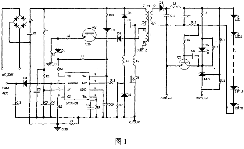
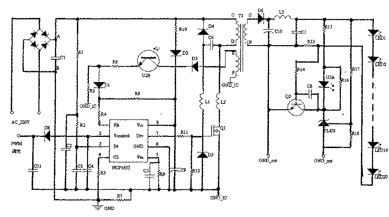
[0017] As shown in Figure 2, the circuit is mainly composed of NCP1653, isolated switching transformer T1, surge absorbing circuit (diode D4, D5, capacitor C6, inductor L1, L2), optocoupler isolator (U2A, U2B) and resistors, capacitors, NCP1653 The CS pin (the 4th pin) detects the current of the branch to change the pulse width to realize PFC. The diode D4, D4, D5, inductor L1, and capacitor C6 absorb the peak voltage generated at the moment the switch tube is turned off, and the inductor L2 absorbs The inrush current generated at the moment the switch tube is turned on, the FB pin (the first pin) of the NCP1653 detects the feedback signal of the optocoupler isolator to realize the output overcurrent and LED open circuit protection functions, the V of the NCP1653 control The pin (the second pin) is connected to the PWM control signal through the diode D8 to realize the LED dimming function.
PUM
 Abstract
Description
Claims
Application Information