Power Factor Corrector Driven by Two Stages of Phase Shift

A technology of power factor correction and phase shifting, which is applied to output power conversion devices, DC power input conversion to DC power output, instruments, etc., can solve problems such as complex control, complex circuit structure, and difficult detection of inductor current, and achieve effective Conducive to the effect of filtering, reducing the number of switching times, and dispersing power consumption

Active Publication Date: 2016-10-05
上海儒竞自动化设备有限公司
View PDF5 Cites 0 Cited by
  • Summary
  • Abstract
  • Description
  • Claims
  • Application Information

AI Technical Summary

Problems solved by technology

[0005] In view of the above-mentioned deficiencies in the prior art, the present invention provides a two-stage phase-shift drive power factor corrector, which is used to solve the problems caused by the complicated circuit structure and the ripple frequency of the boost inductor being equal to the carrier frequency in the prior art. The inductance current detection is difficult and the control is complicated

Method used


Image

  • Power Factor Corrector Driven by Two Stages of Phase Shift
  • Power Factor Corrector Driven by Two Stages of Phase Shift

Examples


Embodiment Construction

[0021] The implementation of the present invention will be illustrated by specific specific examples below, and those skilled in the art can easily understand other advantages and effects of the present invention from the contents disclosed in this specification.

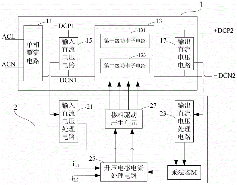
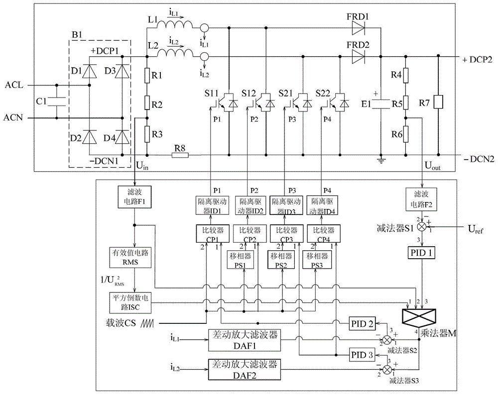
[0022] see Figure 1 to Figure 2 . It should be noted that the structures, proportions, sizes, etc. shown in the drawings attached to this specification are only used to match the content disclosed in the specification, for those who are familiar with this technology to understand and read, and are not used to limit the implementation of the present invention. Limiting conditions, so there is no technical substantive meaning, any modification of structure, change of proportional relationship or adjustment of size, without affecting the effect and purpose of the present invention, should still fall within the scope of the present invention. The disclosed technical content must be within the scope covered. At the sa...


PUM


Abstract

The invention provides a two-stage phase shift-driven power factor corrector which comprises a power unit and a control unit which matches the power unit. The power unit as a whole is two-stage staggered structural power sub-circuits. Each stage of power subcircuit contains two power devices connected in parallel, and inputs single-phase AC sinusoidal voltage, outputs direct voltage for power supply and generates an input voltage signal, an output DC voltage signal and a boost inductive current signal. The control unit inputs a direct voltage reference signal and the above three routes of signals from the power circuits. By a power-factor correction algorithm, four routes of phase shift-driven pulse signals which respectively have 1 / 4 switching period for phase shift are generated to be used for correspondingly driving the four power devices in the power unit, controlling on-off of the four power devices and realizing power-factor correction. According to the invention, the circuit structure is simple, thus being conducive to miniaturization design of an inductor. Meanwhile, switching loss and conduction loss of the power devices are reduced, thus being conducive to type selecting and heat radiation processing of the power devices.

Description

technical field [0001] The invention relates to a power factor corrector, in particular to a two-stage phase-shift driven power factor corrector. Background technique [0002] A single-phase power factor corrector (Power Factor Correction, PFC), that is, an AC-DC converter, inputs an AC voltage to obtain a DC voltage and a sinusoidal input current. With the promotion and application of frequency conversion home appliances (such as: communication power supply and frequency conversion air conditioner), single-phase power factor correctors have been widely used, including: single-phase passive power factor corrector (PPFC) and single-phase active power factor corrector (APFC). [0003] With the promotion and application of high-power frequency conversion air conditioners, etc., it is necessary to introduce high-power single-phase APFC. So far, the following alternative circuits have appeared in total: The first scheme: multi-level interleaved APFC; the advantage of the first ...

Claims


Application Information

Patent Timeline
Patent Type & Authority Patents(China)
IPC IPC(8): H02M1/42H02M3/157
CPCY02B70/10
Inventor 杨进宝杨喜军杨兴华刘极上颜道丹张联柱
Owner 上海儒竞自动化设备有限公司
Why Eureka
Try Eureka