Power factor correction control circuit and power adapter

A power factor correction and control circuit technology, applied in the field of electronics, can solve the problems of energy waste, high cost, low characteristics, etc., and achieve the effects of reducing manufacturing cost, reducing total harmonic distortion, and improving utilization rate

Active Publication Date: 2017-03-01
GENERAL LUMINAIRES SHANGHAI LTD
View PDF3 Cites 0 Cited by
  • Summary
  • Abstract
  • Description
  • Claims
  • Application Information

AI Technical Summary

Problems solved by technology

Although this power factor correction control circuit in the prior art can play the role of overcurrent protection, because the circuit is realized by an optical coupling device, it has a large volume and high cost, and due to the use of a multiplication circuit , causing the output current of the entire circuit to contain harmonics of the input voltage, resulting in high total harmonic distortion (Total Harmonic Distortion, THD) of the circuit, resulting in low power factor (Power Factor, PF) characteristics, resulting in waste of energy

Method used


Image

  • Power factor correction control circuit and power adapter
  • Power factor correction control circuit and power adapter
  • Power factor correction control circuit and power adapter

Examples


Embodiment 1

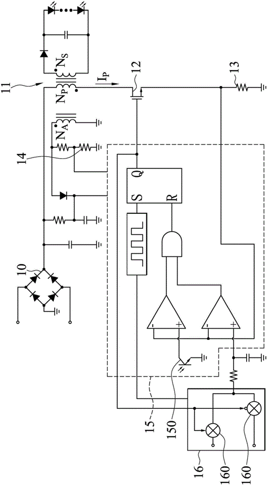
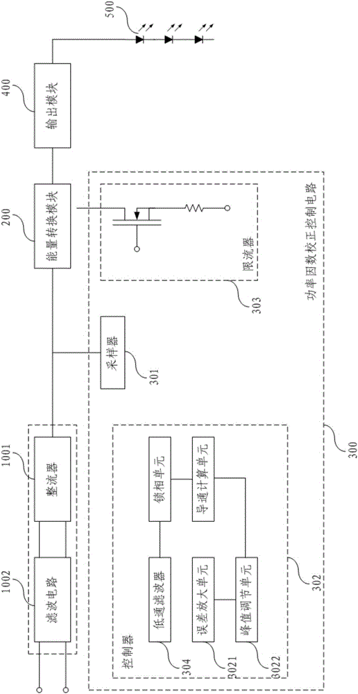
[0040] Such as image 3 and Figure 5As shown, the present embodiment provides a power factor correction control circuit 300, including a sampler 301, a controller 302, and a current limiter 303, and the sampler 301, the controller 302, and the current limiter 303 are sequentially connected in a circuit; its features In that: the controller 302 includes an error amplification unit 3021, a peak adjustment unit 3022, a conduction calculation unit 3023, and a phase-locking unit 3024 connected in sequence; the sampler 301 is connected to the phase-locking unit 3024; the The current limiter 303 is connected to the error amplification unit 3021 and the conduction calculation unit 3023 respectively. Those skilled in the art can understand that the power factor correction control circuit 300 is used in a power adapter and is used to adjust the output signal of the power adapter. The power adapter includes an input module 100 , an energy conversion module 200 and an output module 400...

Embodiment 2

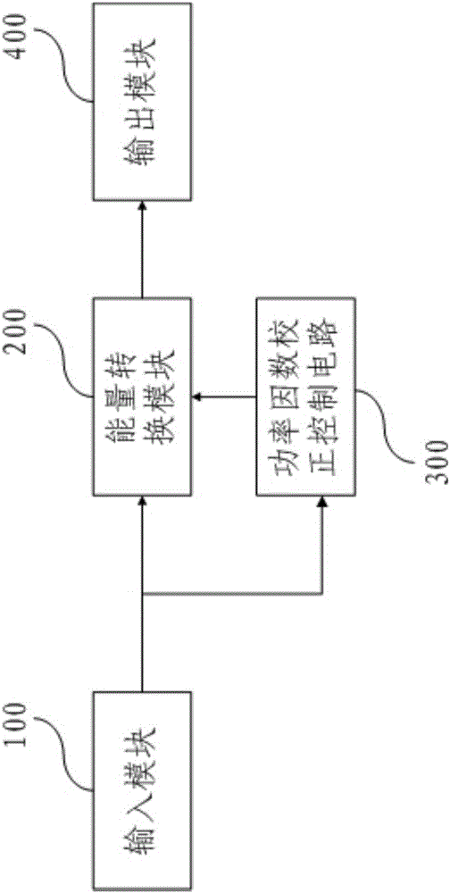
[0048] Such as figure 2 As shown, this embodiment provides a power adapter, including an input module 100, an energy conversion module 200, and an output module 400 connected in sequence; it is characterized in that it also includes a power factor correction control module; the energy conversion module 200 is provided with An input terminal and a control terminal; the power factor correction control module is connected between the input terminal and the output terminal, and the circuit structure of the power factor correction control module is as described in the first embodiment. The power factor correction control module generates a corresponding correction signal U16 according to the input signal received by the energy conversion module 200 and sends it to the control terminal, so as to correct and control the energy conversion module 200, and then adjust the power adapter circuit. Power factor characteristics, improve energy utilization.

[0049] Further, the input modul...


PUM


Abstract

The invention discloses a power factor correction control circuit and a power adapter. The power factor correction control circuit comprises a sampler, a controller and a current limiter. The sampler, the controller and the current limiter are sequentially in circuit connection. The controller comprises an error amplifying unit, a peak value adjusting unit, a conduction calculation unit and a phase locking unit, wherein the error amplifying unit, the peak value adjusting unit, the conduction calculation unit and the phase locking unit are sequentially in circuit connection. The sampler is connected with the phase locking unit. The current limiter is connected with the error amplifying unit and the conduction calculation unit respectively. The power adapter comprises an input module, an energy conversion module and an output module, wherein the input module, the energy conversion module and the output module are sequentially in circuit connection. The energy conversion module is provided with an input end, a control end and the power factor correction control circuit. The power factor correction control circuit is connected between the input end and the output end. The power factor correction control circuit is higher in power factor property, lowers the manufacturing cost and improves the electric energy utilization rate.

Description

technical field [0001] The invention relates to the field of electronic technology, in particular to a power factor correction control circuit and a power adapter for electronic equipment such as liquid crystal displays, televisions, and light-emitting diode lamps. Background technique [0002] In order to provide suitable and stable power for electronic equipment, a power adapter is usually configured in the electronic equipment, and the power adapter mostly uses a pulse width modulation (Pulse Width Modulation, PWM) method to control the voltage value or current value of the output power supply. Power Factor (PF) refers to the relationship between effective power and total power consumption (apparent power), that is, the ratio of effective power divided by total power consumption (apparent power), used for constant power The degree of effective utilization is also one of the important indicators of the characteristics of the constant power adapter. In order to improve the...

Claims


Application Information

Patent Timeline
Patent Type & Authority Patents(China)
IPC IPC(8): H02M1/42H02M3/335
CPCY02B70/10
Inventor 樊志坚
Owner GENERAL LUMINAIRES SHANGHAI LTD
Why Eureka
Try Eureka