Curing spray printing combination

A combined device and top spray technology, applied in the directions of spray device, spray device, printing, etc., can solve the problems of cumbersome equipment operation and control, affecting rolling rhythm, poor temperature adaptability, etc., and achieve simple and reliable equipment maintenance and printing rhythm. The effect of shortening and reducing the repair rate

Active Publication Date: 2010-08-11
BAOSHAN IRON & STEEL CO LTD
View PDF1 Cites 0 Cited by
  • Summary
  • Abstract
  • Description
  • Claims
  • Application Information

AI Technical Summary

Problems solved by technology

[0005] 1. Poor temperature adaptability: Most of the existing inkjet printers use fan cooling, or even do not use active cooling, so the adaptability to temperature is poor, so that the inkjet printer cannot adapt to the higher operating environment temperature and high temperature volume temperature
[0006] 2. Long printing cycle: Most of the existing inkjet printing machines adopt the scheme of single printing equipment combined with articulated robots, so that the top spraying and side spraying are carried out successively, resulting in the inability to shorten the printing cycle and affecting the rolling rhythm. Optimize and speed up
[0007] 3. The structure is more complicated: Although the existing jet printing machine adopts the synchronous scheme of top spraying and side spraying, its mechanical combination design is relatively complicated, the operation and control of the equipment is cumbersome, and it will bring difficulties to equipment maintenance
[0008] In order to solve the above problems, Baosteel applied to the National Patent Office for the invention patent "Spray Printing Combination Device" (patent application number: 200510024100.9). The simultaneous printing of the device achieves the expected effect of the invention patent, but it needs to use two arms to carry the top spraying device and the side spraying device respectively. Although the side spraying and top spraying achieve simultaneous printing, the trajectory of the side spraying and the top spraying do not overlap. The structure is still somewhat complicated

Method used


Image

  • Curing spray printing combination
  • Curing spray printing combination
  • Curing spray printing combination

Examples


specific Embodiment approach

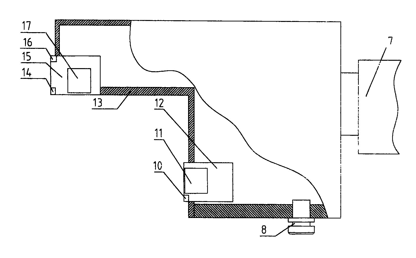
[0025] As shown in Figure 3, it is the first embodiment of the curing jet printing combination device of the present invention. In this embodiment, the top spray assembly 15 and the side spray assembly 12 are connected at right angles in a box body 13, and the box body 13 is connected and installed on the arm. 7 on.

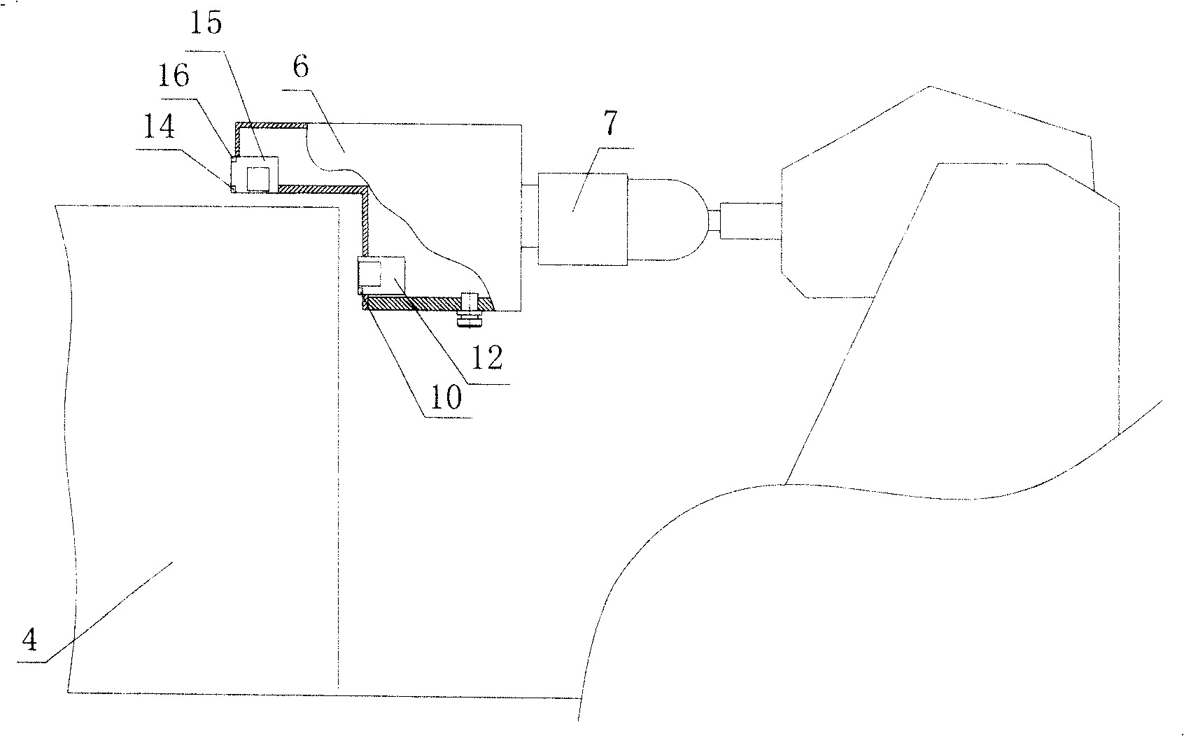
[0026] As shown in Figure 4, it is the second embodiment of the curing jet printing combination device of the present invention. In this embodiment, the top spray assembly 15 and the side spray assembly 12 are respectively installed in a separate box body 9 and a box body 19. The box body 9 and the box body 19 are connected together at right angles through the connecting plate 18, and the connecting plate 18 is then connected and fixedly installed on the arm 7.

[0027] In the two embodiments, the horizontal distance and the longitudinal distance between the top spray assembly 15 and the side spray assembly 12 are all adjustable, that is, the top spray assembly 1...


PUM


Abstract

The invention relates to an assembled device of solidification spray printing used for labeling, which comprises a top-spraying assembly and a side-spraying assembly connected in a right angle or installed in a case, and also installed in two cases respectively and connected to a spray printing wrist to carry out the top-spraying and the side-spraying to a steel coil simultaneously. The top-spraying assembly comprises an upper top-spaying inductor and a lower top-spraying inductor as well as a top-spraying gun assembly arranged in the case. The side-spraying assembly comprises a side-sprayinginductor and a side-spraying gun assembly arranged in the case. Each case is provided with an interface, through which cooling air enters into the case to reduce and maintain the temperature in the case. The device of the invention can realize side-spraying and top-spraying at the same time and the coincidence of the top-spraying track and the side-spraying track. The device has a simple structure, which can be applied to a higher operation environmental temperature and a high temperature coil temperature and also meets the requirements in shorter time of the rolling recycle.

Description

technical field [0001] The invention relates to a curing jet printing combination device, in particular to a curing jet printing combination device applied to steel coil labels. Background technique [0002] The spray printing equipment is a fully automatic marking system controlled by a computer, which directly forms marks on the side surface and top surface of the steel coil by spraying dot matrix. At present, the hot-rolling production lines of domestic and foreign iron and steel enterprises generally use dot-matrix inkjet printing for hot-steel coil labeling. Dot-shaped paint is sprayed on the position to form characters with dots. Because the jet printer also includes a sensor and has a relatively large mass, the side spray on the side surface of the steel coil and the top spray on the top surface of the steel coil are mostly separately controlled by the jet printer. [0003] At present, countries such as Denmark and Japan monopolize the technology and integrated prod...

Claims


Application Information

Patent Timeline
Patent Type & Authority Patents(China)
IPC IPC(8): B41J3/413B05B1/00B41J2/01
CPCB41J3/4073B41J3/413
Inventor 王军
Owner BAOSHAN IRON & STEEL CO LTD
Why Eureka
Try Eureka