Acceleration sensor
An acceleration sensor and angle technology, which is applied in the directions of measuring acceleration, multi-dimensional acceleration measurement, speed/acceleration/impact measurement, etc., can solve the problems of inability to distinguish detection frames and large acceleration detection errors, etc.
- Summary
- Abstract
- Description
- Claims
- Application Information
AI Technical Summary
Problems solved by technology
Method used
Image

Examples
Embodiment approach 1
[0046] First, the main configuration of the acceleration sensor of this embodiment will be described.
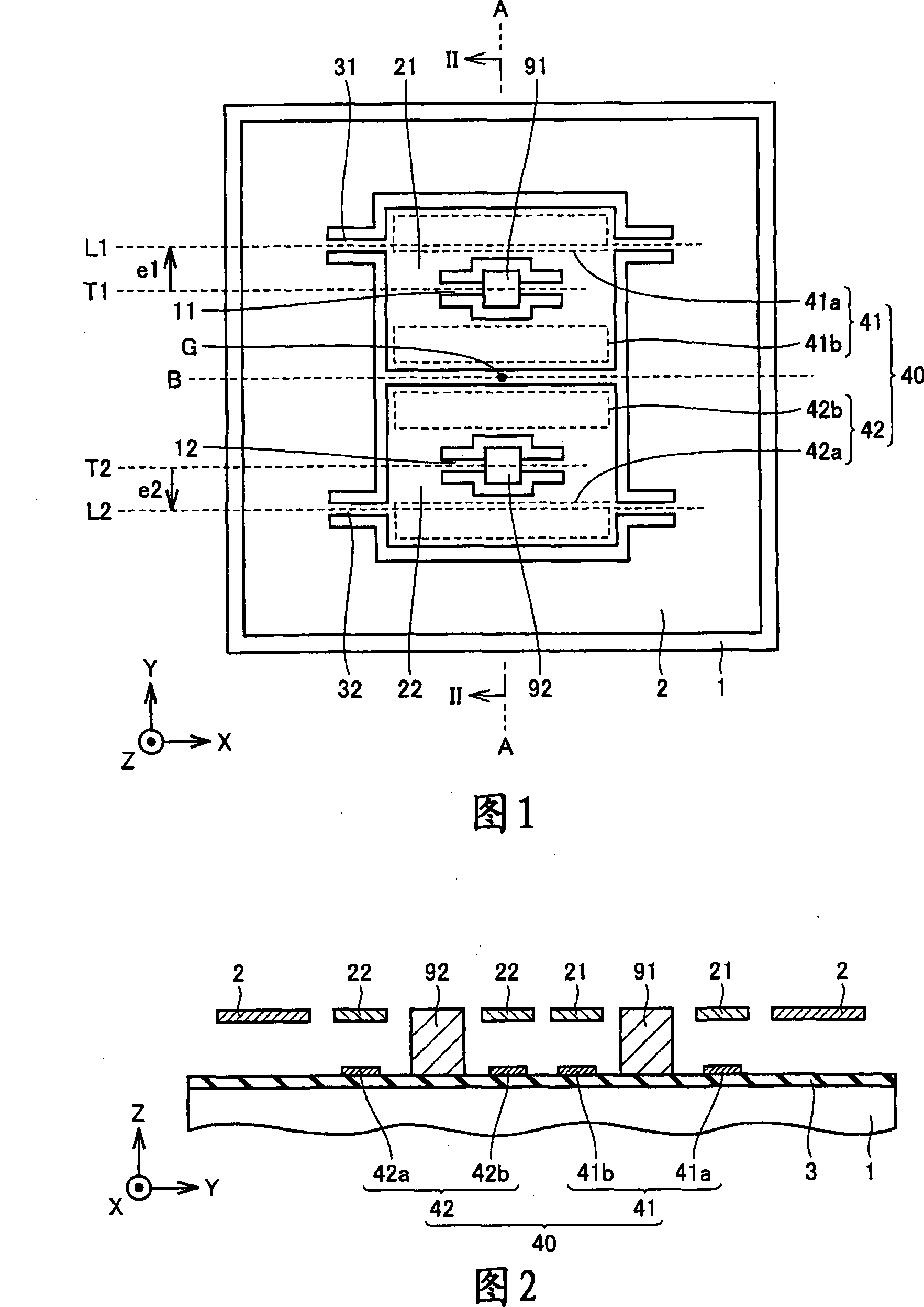
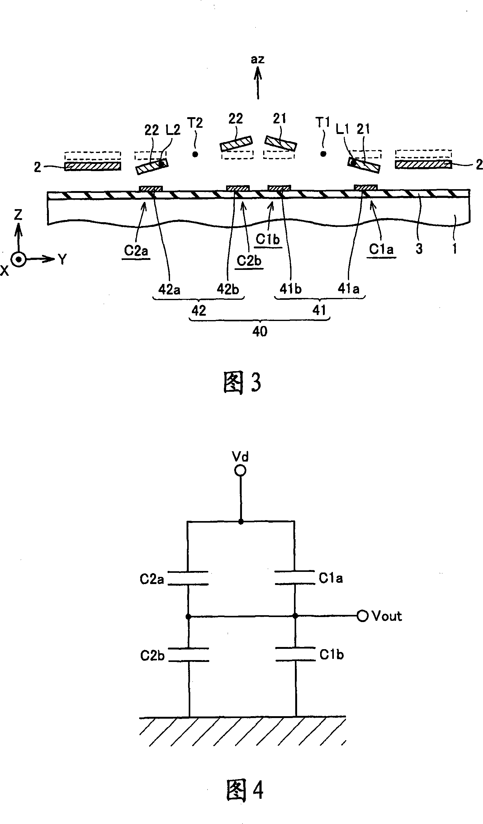
[0047] Referring to FIG. 1 and FIG. 2 , for the convenience of description, the coordinate axes X-axis, Y-axis and Z-axis are introduced. In Figure 1, the X-axis is the positive axis along the right direction along the horizontal direction, the Y-axis is the positive axis along the vertical upper direction, and the Z-axis is the positive direction perpendicular to the upper side of the paper. axis. In addition, the direction of the Z-axis coincides with the acceleration direction that is the measurement target of the acceleration sensor of this embodiment.
[0048] The acceleration sensor of this embodiment mainly includes a substrate 1, first and second torsion beams 11, 12, first and second detection frames 21, 22, a plurality of detection electrodes 40, first and second connecting beams 31, 32, And the inertial mass body 2.
[0049] As the substrate 1, a silicon substr...
Embodiment approach 2
[0106] Referring to FIGS. 14 and 15 , in the acceleration sensor of the present embodiment, excitation electrodes 5 are formed on substrate 1 so as to face inertial mass 2 .
[0107] Other than that, the configuration of the present embodiment is the same as that of the above-mentioned first embodiment, so the same elements are denoted by the same reference numerals, and description thereof will be omitted.
[0108] According to the present embodiment, by applying a voltage between the excitation electrode 5 and the inertial mass 2 , as shown by the arrow in FIG. 15 , an electrostatic force that attracts the inertial mass 2 toward the substrate 1 can be generated. That is, the inertial mass 2 can be electrostatically driven in the thickness direction of the substrate 1 . This electrostatic drive can generate the same displacement as that of the inertial mass 2 when the acceleration az in the thickness direction of the substrate 1 is applied to the acceleration sensor. Therefo...
Embodiment approach 3
[0110] Referring to FIG. 16 , the acceleration sensor of this embodiment has anchor points 90 and support beams 4 provided on a substrate 1 .
[0111] One end of the support beam 4 is supported on the base plate 1 through the anchor point 90 . The other end of the support beam 4 supports the inertial mass 2 .
[0112] The support beam 4 has a 1st support beam 4X and a 2nd support beam 4Y. The first support beam 4X has a shape that can be easily elastically deformed in the Z-axis direction, and hardly elastically deformed in the X-axis direction. The second support beam 4Y has a shape that can be easily elastically deformed in the Z-axis direction, and hardly elastically deformed in the Y-axis direction. Therefore, as a whole, the support beam 4 is configured to be easily elastically deformed in the Z-axis direction and difficult to be elastically deformed in the XY in-plane direction.
[0113] Other than that, the configuration of this embodiment is the same as that of Embo...
PUM
 Abstract
Description
Claims
Application Information
 - R&D Engineer
- R&D Manager
- IP Professional
- Industry Leading Data Capabilities
- Powerful AI technology
- Patent DNA Extraction
Browse by: Latest US Patents, China's latest patents, Technical Efficacy Thesaurus, Application Domain, Technology Topic.
© 2024 PatSnap. All rights reserved.Legal|Privacy policy|Modern Slavery Act Transparency Statement|Sitemap