
System and method for optimized spatio-temporal sampling

An optimized, time-framed technology that can be used in radio wave measurement systems, applications, and re-radiation to solve problems such as image blurring

Active Publication Date: 2008-07-30
SONOSITE
View PDF0 Cites 4 Cited by
  • Summary
  • Abstract
  • Description
  • Claims
  • Application Information

AI Technical Summary

Problems solved by technology

[0007] A drawback of the compositing method used today is that it introduces temporal artifacts, which are introduced into the final image, which in turn makes the image blurry to the user

Method used


Image

  • System and method for optimized spatio-temporal sampling
  • System and method for optimized spatio-temporal sampling
  • System and method for optimized spatio-temporal sampling

Examples


Embodiment Construction

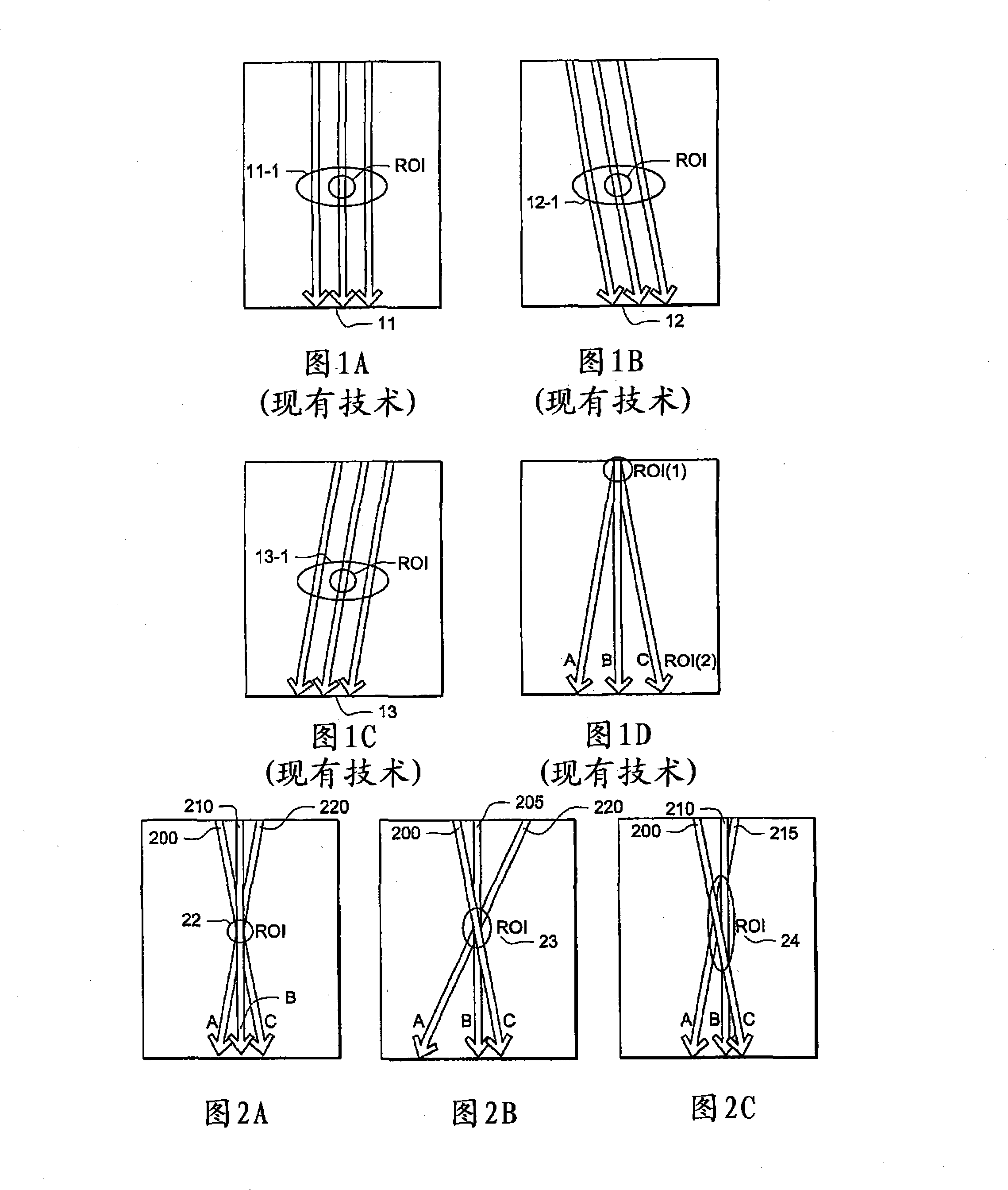
[0015] 1A to 1C show examples of frame interleaving spatial composition in the prior art. In Fig. 1A, the beam ray is steered straight, while in Figs. 1B and 1C, the beam ray is steered to the left and to the right, respectively. This demonstrates the most common spatial composite ray emission sequence, which consists of acquiring separate frames for each steering direction. For example, frame 11 shows the full frame of the straight ray 11-1 (actually only three of them are drawn), followed by the full frame 12 of the ray 12-1 that turns to the left, and then the ray 13- that turns to the right. 1 full frame 13. These three frames are then composited together to form the final image. This compounding is difficult because the target may have moved between frames, making the target look different for subsequent frames. In order to achieve the best image, it is important to ensure that the different frames are aligned with each other before combining. In some cases, additional post-p...


PUM


Abstract

The present invention is directed to a system and method for spatial compounding on an ultrasound platform to achieve optimized spatio-temporal sampling. This is accomplished by a system and method for mixing the order of steered and straight rays fired within a frame. In one embodiment this is accomplished by changing the firing sequence so that the target region is sampled in subsequent lines as opposed to subsequent frames. Using this approach it is possible to minimize the temporal image artifacts caused by the compounding process. This effectively changes the ray firing sequence to move the location of minimal temporal difference to the desired target point.

Description

[0001] Cross-references to related applications [0002] This application requires the United States Provisional Patent Application No. 60 / 886,877 filed on January 26, 2007 under the title "SYSTEM ANDMETHOD FOR TEMPORAL COHERENCE SPATICAL SAMPLING" and on May 16, 2007 under the title "SYSTEM AND METHOD FOR OPTIMIZED SPATIO-TEMPORALSAMPLING" US Utility Patent Application No. 11 / 749,319, the entire content of which is incorporated herein by reference. Technical field [0003] The present disclosure relates to ultrasound imaging, and more specifically to systems and methods for optimized spatiotemporal sampling. Background technique [0004] Spatial composite is a method of creating ultrasound images by editing multiple views or angles. Each view is obtained from multiple lines of sight from different angles. This is different from traditional ultrasound imaging that uses a single line of sight. Views from multiple angles are combined to create a single image, thereby enhancing solid...

Claims


Application Information

Patent Timeline
Patent Type & Authority Applications(China)
IPC IPC(8): G03B42/06A61B8/00
CPCA61B8/08G01S7/52085G01S15/8995G01S15/8993
Inventor 安德鲁·K·伦德伯格
Owner SONOSITE
Features
  • Generate Ideas
  • Intellectual Property
  • Life Sciences
  • Materials
  • Tech Scout
  • Unparalleled Data Quality
  • Higher Quality Content
  • 60% Fewer Hallucinations
Learn More