Generator

A generator and generator stator technology, which is applied to motors, electric vehicles, electrical components, etc., can solve the problems of inconvenient installation and use in specific occasions, low power generation efficiency, complex structure, etc., and achieves light weight, simple structure, and application range. wide effect

Inactive Publication Date: 2012-11-07
韩玉金
View PDF0 Cites 0 Cited by
  • Summary
  • Abstract
  • Description
  • Claims
  • Application Information

AI Technical Summary

Problems solved by technology

[0002] As we all know, the generator shafts of the generators sold on the market are all solid shafts, and the power generation efficiency is low at low speed, the structure is complex, the volume is large, and it is not easy to install and use in specific occasions.

Method used


Image

  • Generator
  • Generator
  • Generator

Examples


Embodiment 1

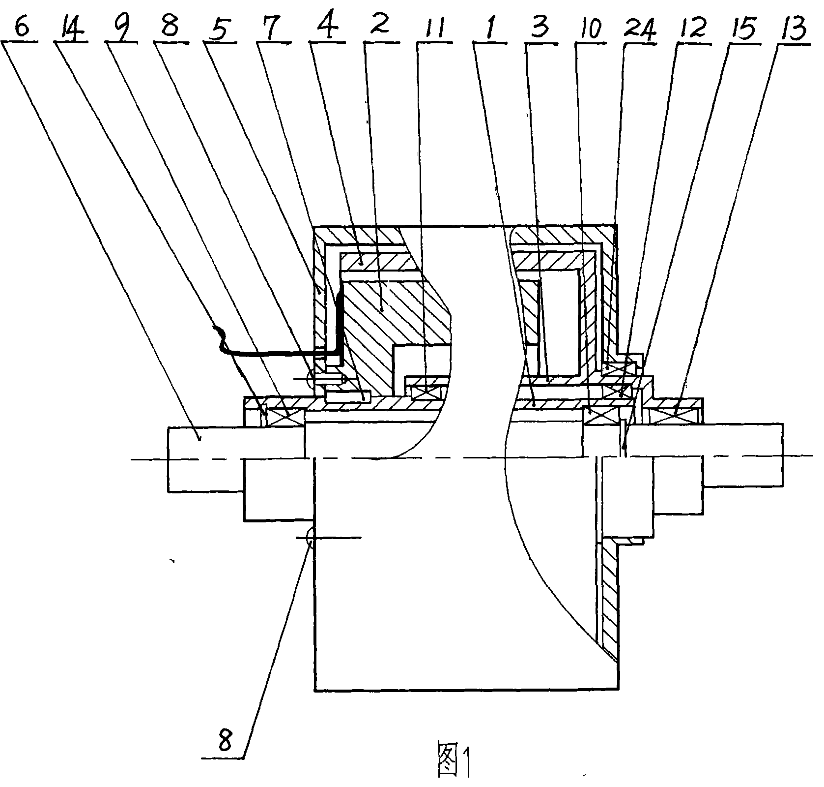
[0026] Embodiment 1: Take wind power generation as an example for illustration.

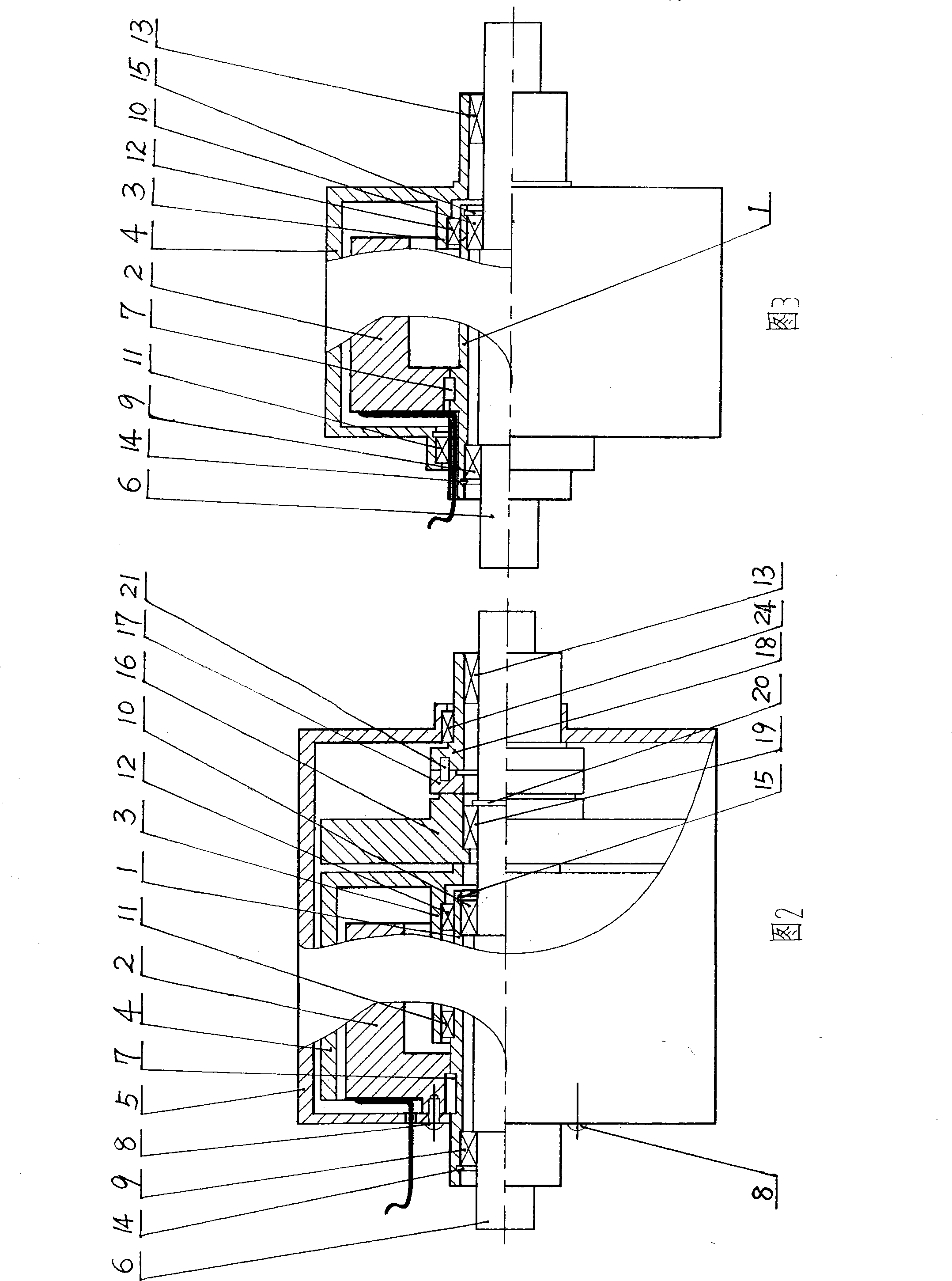
[0027] Such as figure 1 , image 3 , Figure 4 , Figure 5 , Figure 6 As shown: the generator stator shaft 1 and the rotor shaft 3 are hollow shafts, the generator rotor shaft 3 and the generator rotor 4 are fixedly connected, the generator stator shaft 1 is fixedly connected with the generator stator 2, and is fixed by a pin placed axially 7 is fixed, the generator stator 2 and the stator casing 5 are fixedly connected by bolts 8, one end of the stator casing 5 is supported by a bearing 24 on the output side of the generator rotor shaft 3, and the generator stator shaft 1 and the rotor shaft 3 have a through shaft 6. The through shaft 6 is respectively supported in the generator stator shaft 1 through two bearings 9 and 10 at both ends of the generator stator shaft 1. The bearings 9 and 10 are axially fixed by two retaining springs 14 and 15 respectively. The generator rotor 4. The two bea...

Embodiment 2

[0029] Embodiment 2: Take electric bicycle pedal power generation as an example for illustration.

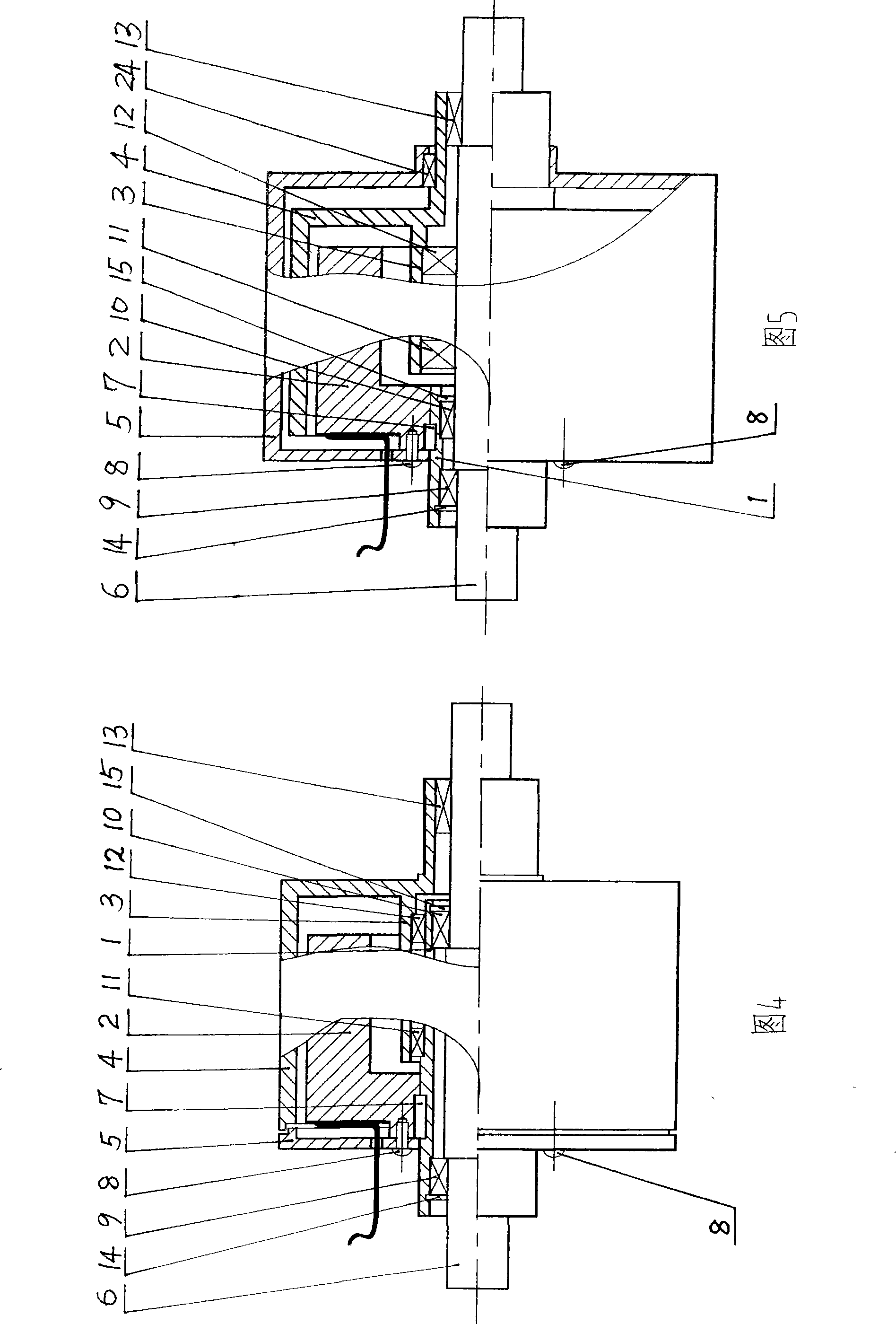
[0030] Such as figure 1 , image 3 , Figure 4 , Figure 5 , Figure 6 , Figure 8 As shown: the generator stator shaft 1 and the rotor shaft 3 are hollow shafts, the generator rotor shaft 3 and the generator rotor 4 are fixedly connected, the generator stator shaft 1 is fixedly connected with the generator stator 2, and is fixed by a pin placed axially 7 is fixed, the generator stator 2 and the stator casing 5 are fixedly connected by bolts 8, one end of the stator casing 5 is supported by a bearing 24 on the output side of the generator rotor shaft 3, and the generator stator shaft 1 and the rotor shaft 3 have a through shaft 6. The through shaft 6 is respectively supported in the generator stator shaft 1 through two bearings 9 and 10 at both ends of the generator stator shaft 1. The bearings 9 and 10 are axially fixed by two retaining springs 14 and 15 respectively. The ...

Embodiment 3

[0033] Embodiment 3: Taking an electric bicycle as an example, the generator is changed to be driven by a motor for illustration.

[0034] Such as figure 1 , image 3 , Figure 4 , Figure 5 , Figure 6 , Figure 8 Shown: the alternator is changed into electric motor drive. When the corresponding current is passed into the coil of the generator stator 2, the generator rotor 4 rotates, and the output end of the generator rotor shaft 3 drives the sprocket to rotate, and the electric bicycle advances, but at this time, due to the generator stator shaft 1 and the rotor shaft 3 It is a hollow shaft, the generator stator shaft 1 and the rotor shaft 3 have a through shaft 6, and one end of the generator rotor shaft 3 and the through shaft 6 is fixed with a first bearing 13, and the first bearing 13 adopts a one-way bearing (or a One-way clutch instead of using) disengages, the through shaft 6 does not turn, then the pedal crank and the pedals fixed on the two ends of the throug...


PUM


Abstract

The invention relates to a generator. A stator spindle and a rotor spindle of the generator are both hollow spindles; a rotor of the generator is sleeved outside the stator or sleeved on the lateral surface of a stator; the stator of the generator is fixedly connected with the stator spindle of the generator; a through-spindle is arranged inside the stator spindle and the rotor spindle of the generator; the through-spindle is supported in the stator spindle and the rotor spindle of the generator through a bearing; the rotor of the generator is supported on the stator spindle of the generator or the through-spindle through the bearing; the rotor of the generator rotates to generate electricity under external force. The generator can also be arranged in series connection for use, and can also be turned into a motor by electrifying current to a stator coil. The invention has the advantages that the weight is light, the structure is simple, and efficiency is high when the generator runs at a low speed under the power generation state; the torque is big when the generator runs at a low speed under the electric state, the practicality is strong, the installation is convenient, the cost is low, and the application range is wide; the generator can be widely used in such fields as power assistant vehicle, electric motor car, electric automobile, hybrid electric vehicle, hybrid power motorcycle, power locomotive, ship, spacecraft, wind power generation, steam energy power generation, motive power machine, etc.

Description

technical field [0001] The invention relates to a generator, in particular to a generator with a through-shaft stator and a hollow rotor shaft. Background technique [0002] As we all know, recently, the generator shafts of the generators sold on the market are all solid shafts, and the power generation efficiency is low under low-speed operation, the structure is complicated, and the volume is large, which is not easy to install and use in specific occasions. Contents of the invention [0003] The invention provides a generator to solve the technical problems in the known technology. [0004] The technical solution adopted by the present invention to solve the technical problems existing in the known technology is: a generator, which is composed of a generator stator, a rotor and a shaft, and is characterized in that: the generator stator shaft 1 and the rotor shaft 3 are hollow shafts , the generator rotor shaft 3 is fixedly connected to the generator rotor 4, the gener...

Claims


Application Information

Patent Timeline
Patent Type & Authority Patents(China)
IPC IPC(8): H02K16/00H02K7/00H02K7/08
CPCY02T10/641Y02T10/64
Inventor 韩玉金张宏艳
Owner 韩玉金
Why Eureka
Try Eureka