Supercharge Your Innovation With Domain-Expert AI Agents!

Electronic apparatus and method to control electronic apparatus

一种电子设备、控制器的技术,应用在印刷、产生/分配信号等方向,能够解决增大电磁干扰、增大等问题

Inactive Publication Date: 2008-08-06
SAMSUNG ELECTRONICS CO LTD
View PDF6 Cites 2 Cited by
  • Summary
  • Abstract
  • Description
  • Claims
  • Application Information

AI Technical Summary

Problems solved by technology

[0019] Additionally, the introduction of peak currents increases the amount of energy that increases proportionally to the magnitude of the current, increasing electromagnetic interference (EMI)

Method used


Image

  • Electronic apparatus and method to control electronic apparatus
  • Electronic apparatus and method to control electronic apparatus
  • Electronic apparatus and method to control electronic apparatus

Examples


Embodiment Construction

[0070] Reference will now be made in detail to example embodiments of the present general inventive concept, examples of which are illustrated in the accompanying drawings, wherein like reference numerals refer to like elements throughout. The example embodiments are described below in order to explain the present general inventive concept by referring to the figures.

[0071] FIG. 6 is a block diagram illustrating an electronic device according to example embodiments of the present general inventive concept. FIG. 7 is a block diagram illustrating the second signal generator shown in FIG. 6 . FIG. 8 is a logic circuit diagram illustrating the second signal generator shown in FIG. 7 .

[0072] In addition, FIG. 9 is a waveform diagram illustrating driving pulses generated by the electronic device shown in FIG. 6 . FIG. 10 is a waveform diagram illustrating a change in current according to a driving pulse generated by the electronic device shown in FIG. 6 .

[0073] Specifica...


PUM


Abstract

An electronic device and method for controlling one or more internal units thereof capable of preventing a peak current from being introduced into the internal units of the electronic device when the internal units are simultaneously activated. The electronic device includes: at least one internal unit; and a signal generator for generating a driving pulse having a width gradually changing in an edge region and driving the at least one internal unit. Therefore, the peak current is prevented from being introduced into the internal cells by gradually increasing or decreasing the driving pulses for driving the internal cells as time changes, or by dividing the internal cells into block units and sequentially supplying the driving pulses to the internal cells. unit.

Description

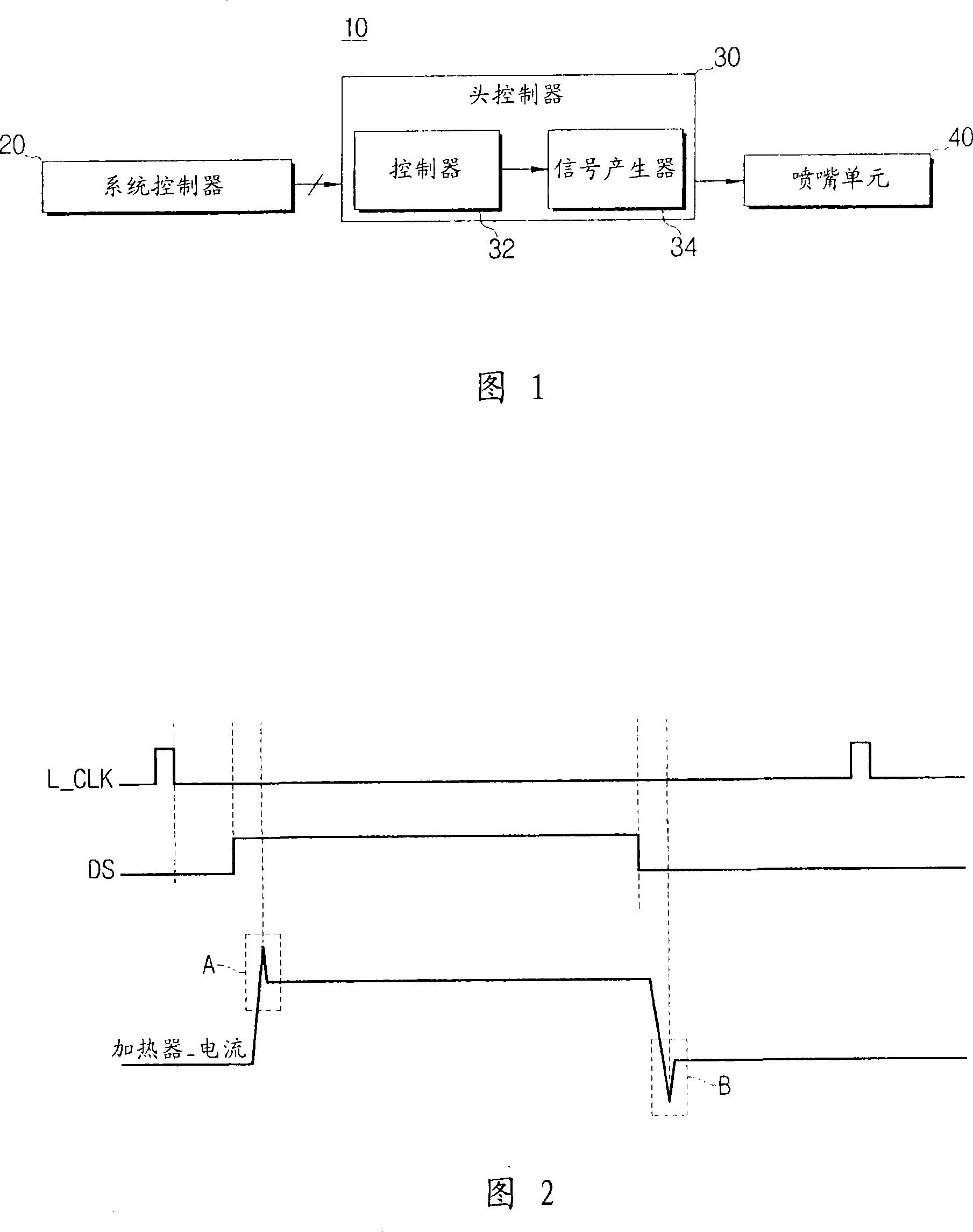
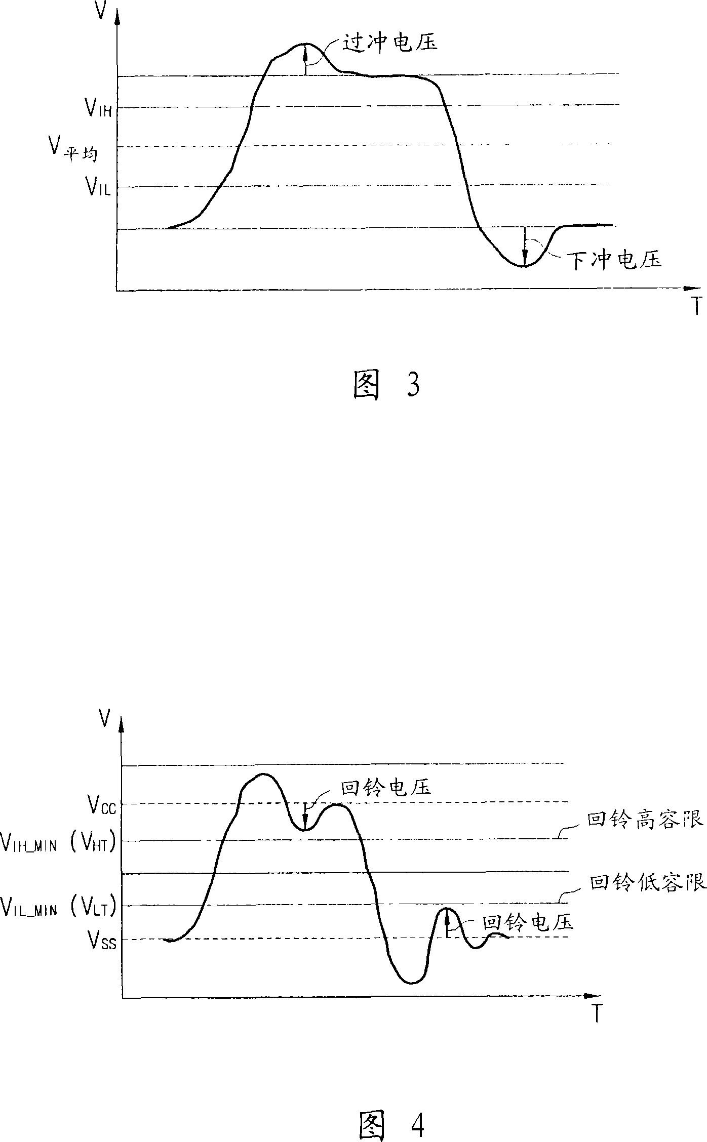
technical field [0001] The present general inventive concept relates to an electronic device and a method for driving one or more internal units thereof, and more particularly to an electronic device capable of operating in the prevents peak currents from being introduced into the internal cells when the internal cells are activated simultaneously. Background technique [0002] Generally, electronic devices include various integrated circuits such as controllers in order to realize various functions, high-speed operation performance, and miniaturization of the devices. [0003] The integrated circuit is driven by simultaneously activating internal elements such as transistors and inverters. In embodiments where internal elements are activated simultaneously, a peak current is induced into said internal elements. [0004] Hereinafter, as an example, an electronic device such as an inkjet printer will be described in order to explain a process of introducing a peak current i...

Claims


Application Information

Patent Timeline
Patent Type & Authority Applications(China)
IPC IPC(8): B41J2/05
CPCB41J2/04573B41J2/0458B41J2/04588G06F1/08G06F1/04G06F1/10
Inventor 全性男韩春九
Owner SAMSUNG ELECTRONICS CO LTD
Features
  • R&D
  • Intellectual Property
  • Life Sciences
  • Materials
  • Tech Scout
  • Unparalleled Data Quality
  • Higher Quality Content
  • 60% Fewer Hallucinations
Learn More