Constant spring hanger

A technology of constant force springs and hangers, which is applied in the direction of springs/shock absorbers, cup springs, pipe supports, etc., and can solve problems such as high manufacturing costs and complex structures

Inactive Publication Date: 2008-08-06
扬州核威碟形弹簧制造有限公司
View PDF1 Cites 14 Cited by
  • Summary
  • Abstract
  • Description
  • Claims
  • Application Information

AI Technical Summary

Problems solved by technology

However, its structure is relatively complex

Method used


Image

  • Constant spring hanger
  • Constant spring hanger

Examples


Embodiment Construction

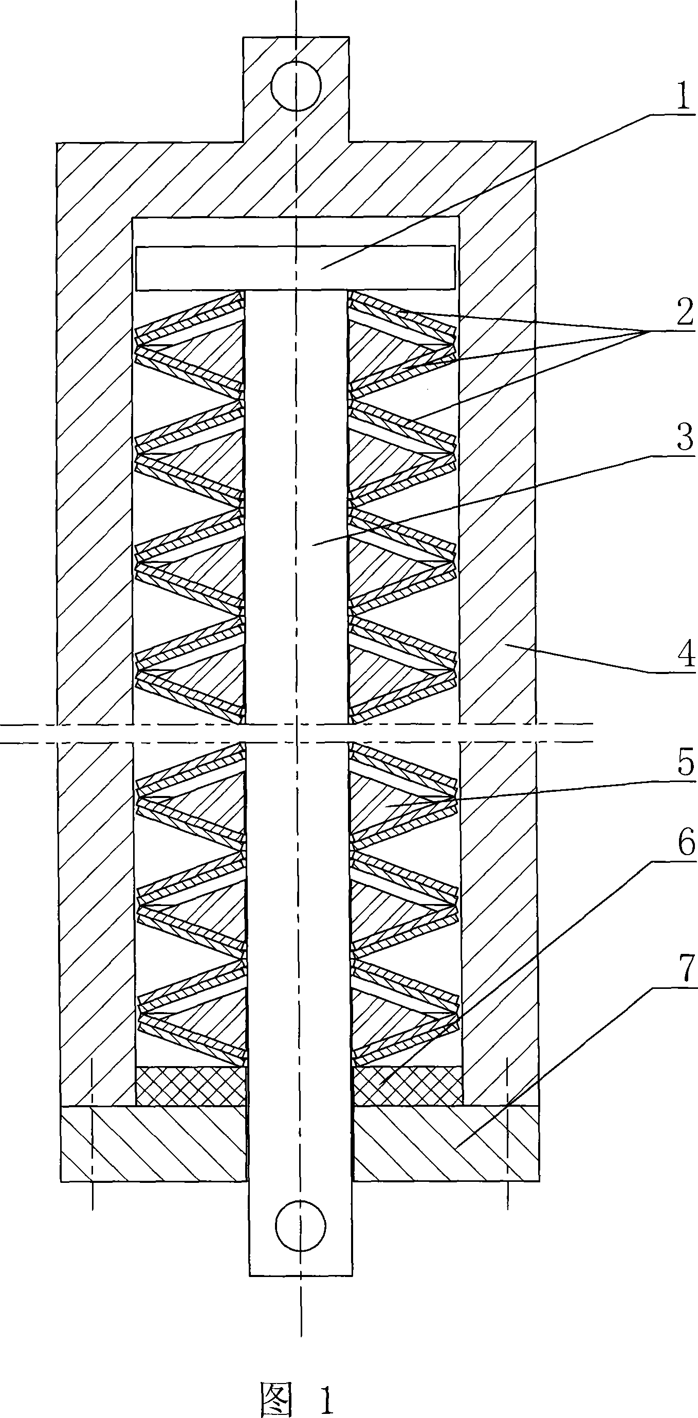
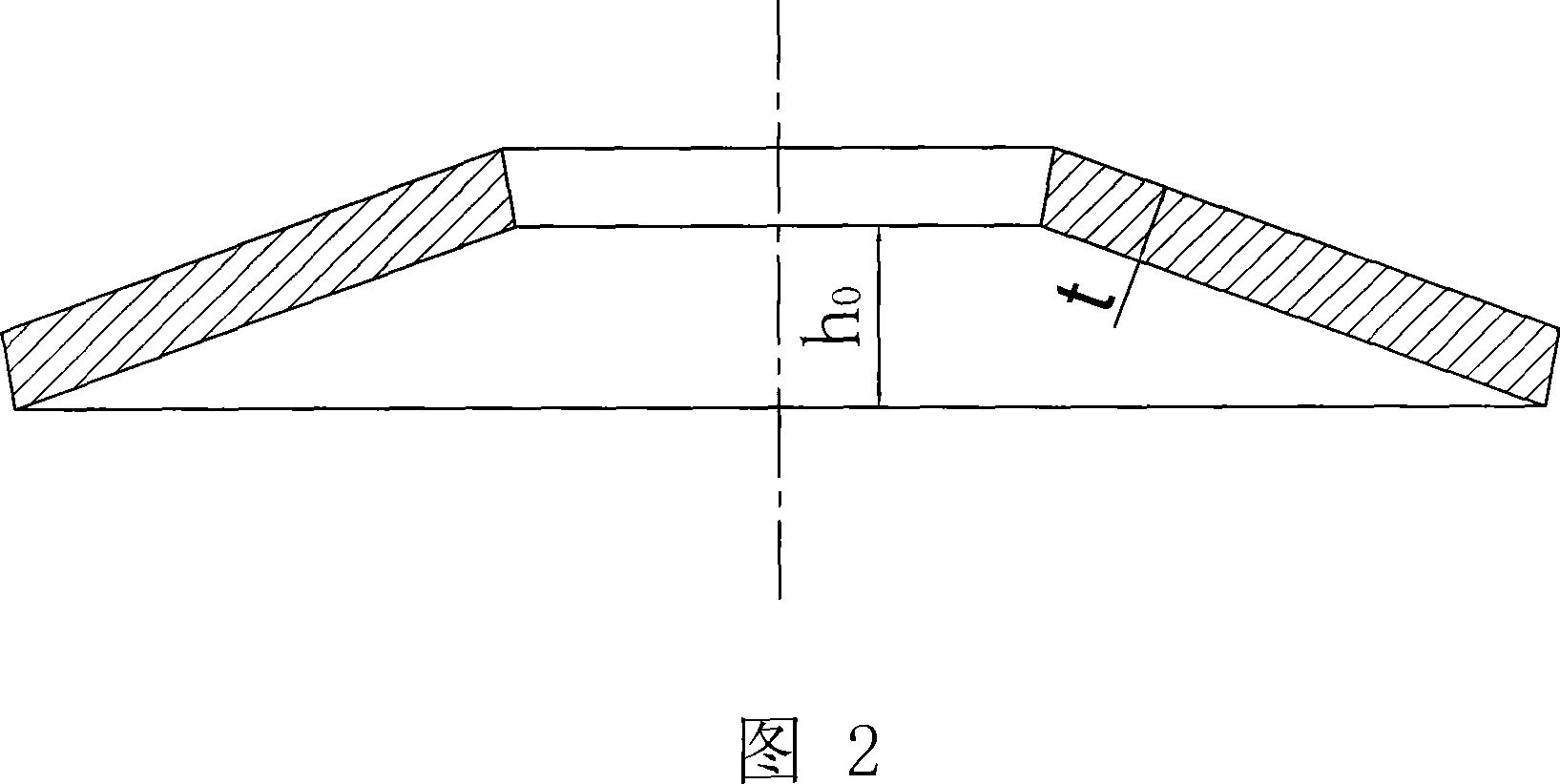
[0009] As shown in the figure, it is a constant force spring hanger, including a housing 4 and a load rod 3. The housing 4 is hollow, the load rod 3 is arranged in the housing 4, and the lower end of the load rod 3 extends from the bottom cover of the housing 4 Outside the housing 4, a pull plate 1 is fixed at the upper end of the load rod 3. A number of disc spring groups are arranged between the pull plate 1 and the bottom cover 7 of the housing 4, and each disc spring group has two pieces. The same disc springs 2 are superimposed (superimposed means that at least two disc springs are stacked together in the same direction); the two adjacent disc spring groups are arranged in opposite directions, and the inner cone of the disc spring 2 The ratio of the height h0 to the thickness t is 1.5-2.0, and the best value is 1.75. A limit block 5 is provided between the two disc spring groups arranged in order to prevent the disc spring 2 from flanging (the arrangement is Refers to the lar...


PUM


Abstract

The invention discloses a constant force spring hanger in the technical field of elastic telescopic machinery, which comprises a casing and a load tie rod, wherein the casing is hollow and the load tie rod is disposed inside the casing. The lower end of the load tie rod penetrates from the bottom cover of the casing out, and a draw plate is fixed at the upper end of the tie rod. A plurality of disc spring assemblies are arranged between the draw plate and the bottom cover of the casing, each disc spring assembly is overlaid by one disc spring or a plurality of the disc springs, two adjacent disc spring assemblies are arranged opposite to each other, ratio of the inner cone height of the disc spring and thickness thereof is 105-2.0, and a limiting stopper capable of preventing the disc spring from flanging is disposed between two disc spring assemblies which are in involution arrangement. The constant force spring hanger employs the characteristic of zero stiffness of the disc springs to fabricate the constant force spring hanger with advantages of simple structure, easy mounting, low fabrication cost and reliable utilization, and can be applied to various situations requiring suspension and support.

Description

Technical field [0001] The invention relates to an elastic telescopic mechanical device, in particular to a constant force spring hanger. Background technique [0002] In the prior art, there is a constant force spring hanger with umbrella structure, its publication number is CN1648504A, which mainly includes a housing, a spring, a load rod, a load plate, a plate shaft, a plate shaft track, a pressure shaft, a rotating frame, Load shaft, boom shaft, pull plate, main shaft, fixed frame, pressure plate, load shaft slide; the fixed frame and the shell form an integral structure, the fixed frame center perpendicular to the load shaft slide, the load shaft slide on both sides There is a downward plane; the two revolving frames pass through a common load axis, one end of the two pull plates is connected through the common pull plate axis, and the other end of the pull plate is connected with the respective pressure axis to form an equilateral quadrilateral that can change the angle ; T...

Claims


Application Information

Patent Timeline
IPC IPC(8): F16L3/21
CPCF16F1/32
Inventor 郭斌徐一鸣
Owner 扬州核威碟形弹簧制造有限公司
Why Eureka
Try Eureka