
Precision machining apparatus and precision machining method

一种精密加工、设备的技术,应用在金属加工设备、金属加工、磨削/抛光设备等方向,能够解决微小调整不够等问题,达到经济制造的效果

Inactive Publication Date: 2008-08-06
TOYOTA JIDOSHA KK
View PDF1 Cites 9 Cited by
  • Summary
  • Abstract
  • Description
  • Claims
  • Application Information

AI Technical Summary

Problems solved by technology

Therefore, in the superfinishing stage, which focuses on making small adjustments to thickness and flatness, sometimes small adjustments are not enough

Method used


Image

  • Precision machining apparatus and precision machining method
  • Precision machining apparatus and precision machining method
  • Precision machining apparatus and precision machining method

Examples


Embodiment Construction

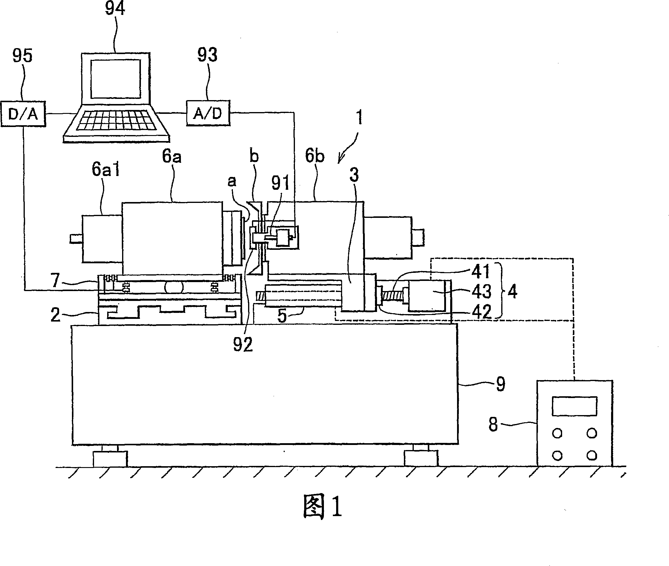
[0055] In the following description and drawings, the invention will be described in more detail by way of exemplary embodiments. Pneumatic actuators are used in the illustrated exemplary embodiment. Alternatively, however, hydraulic actuators may be used. In addition, three or more actuators may be provided depending on the pressure control. Furthermore, in the illustrated exemplary embodiment, the pose control means is subject to feedback control. Of course, alternatively, the lead screw mechanism may be subject to feedback control or both the pose control device and the lead screw mechanism are controlled through the interface circuit.

[0056] Fig. 1 shows a precision machining device 1 according to an exemplary embodiment. The precision machining equipment 1 roughly includes: a rotating device 6a that rotates a grinding target a in a vacuum-suction position; a first support 2 that supports the rotating device 6a; and a second support 3 that supports the rotation of a r...


PUM


Abstract

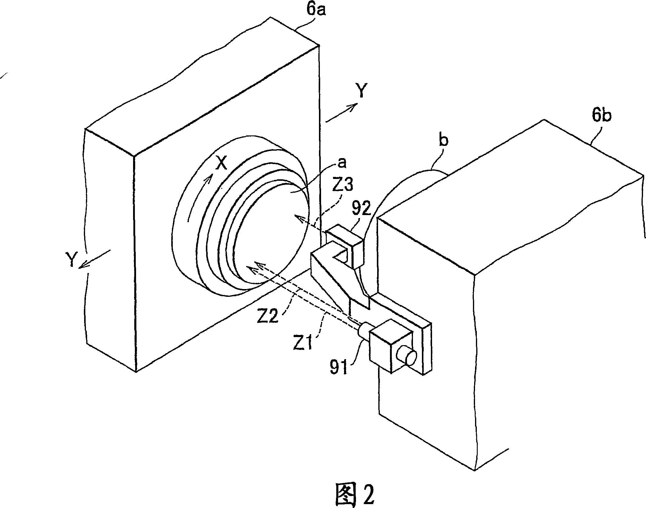
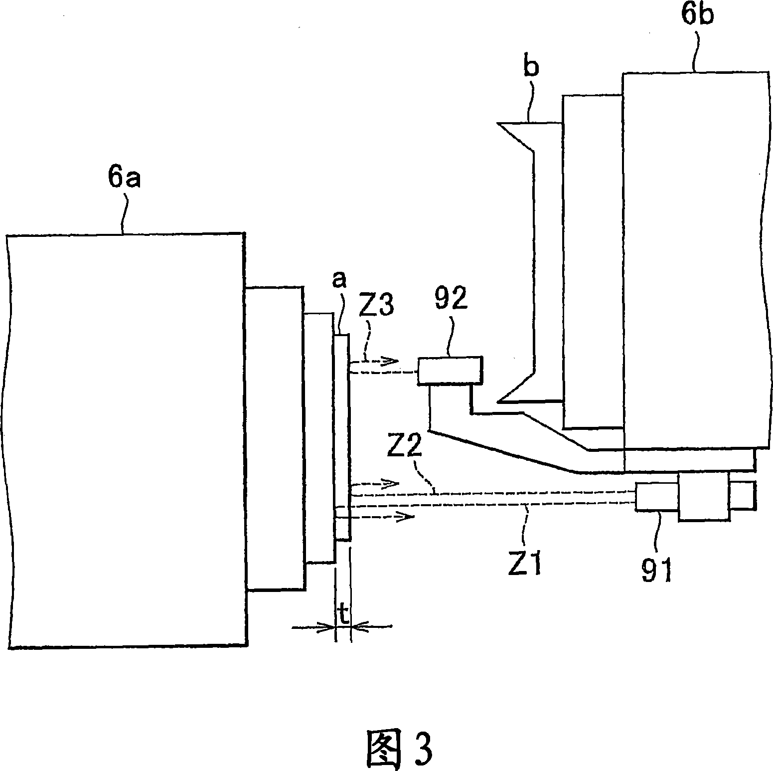
A precision machining apparatus is structured such that a feed-screw mechanism and an actuator are mounted on a second mount which supports a rotating device that rotates a wheel, and grinding is performed while appropriately adjusting the amount of movement of the second mount in a rough grinding stage through an ultra-precision grinding stage. A posture control device is interposed between a first mount and a rotating device that rotates a grinding target body. The thickness and evenness of the grinding target body are measured by an optical probe and the measurement results are sent to a computer. A feedback command is then sent to the posture control device to reduce the difference between target values and the measurement values and posture control is performed accordingly.

Description

technical field [0001] The present invention relates to a precision machining apparatus used when grinding an object to be ground (hereinafter also referred to as "grinding object") requiring precise geometrical accuracy and flatness, such as a silicon wafer or a magnetic disk substrate, and Precision machining method. More specifically, the present invention relates to a precision machining apparatus and a precision machining method capable of controlling the pose of a pose control device and controlling the moving parts forming the precision machining apparatus in all grinding stages from rough grinding to finish grinding The thickness and flatness of the object to be ground are precisely controlled by performing feedback control. Background technique [0002] Recently, there has been an increasing demand for next-generation power devices that are smaller and consume less power. High-precision, multilayer semiconductors used in electronic devices are examples of this. I...

Claims


Application Information

Patent Timeline
Patent Type & Authority Applications(China)
IPC IPC(8): B24B37/04B24B49/04B24B49/12B24B41/06B23Q15/00B23Q15/22B23Q17/20B24B7/04B24B41/047B24B47/12B24B47/14B24B49/02
CPCB24B49/04B24B37/005B24B49/12B24B41/061B24B37/04B24B7/04B23Q15/00
Inventor 神谷纯生岩瀬久雄永池哲也江田弘周立波
Owner TOYOTA JIDOSHA KK
Learn More