
LED road lamp optical system

A technology of LED street lamps and optical systems, applied in the field of optical systems, can solve the problems of unsatisfactory light distribution effect and low utilization rate of light energy, and achieve the effects of reducing glare, enhancing energy saving effect and simple structure

Inactive Publication Date: 2008-08-13
UNIV OF SHANGHAI FOR SCI & TECH
View PDF0 Cites 7 Cited by
  • Summary
  • Abstract
  • Description
  • Claims
  • Application Information

AI Technical Summary

Problems solved by technology

[0004] The present invention aims at the problem of unsatisfactory light distribution effect and low utilization rate of light energy in the existing LED street light optical system, and proposes an LED street light optical system, which adopts a multi-reflector structure and can distribute light energy reasonably and effectively

Method used


Image

  • LED road lamp optical system
  • LED road lamp optical system

Examples


Embodiment Construction

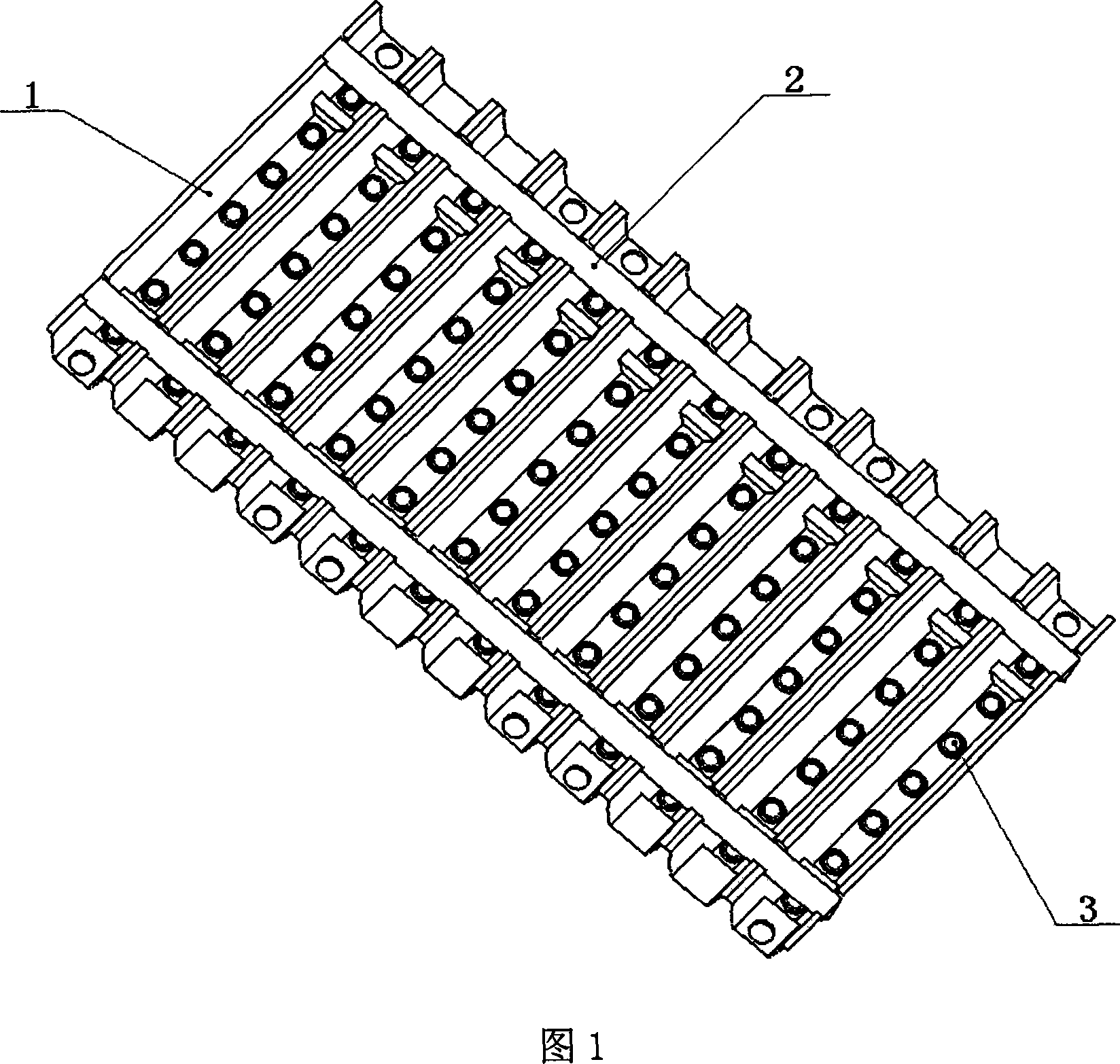
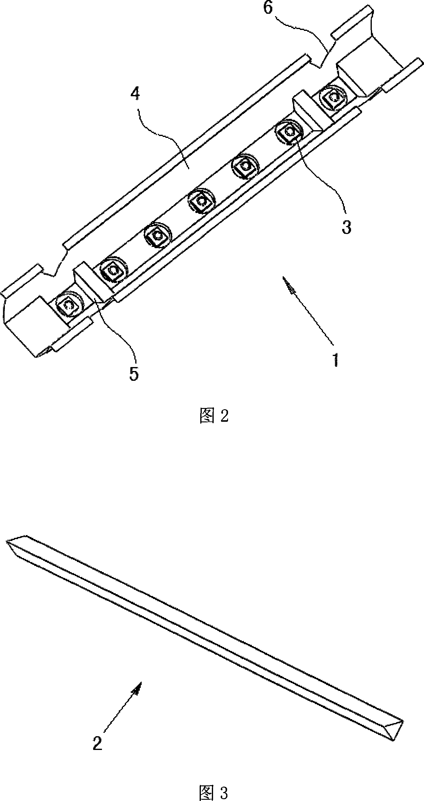
[0014] Figure 1 is a schematic diagram of the overall structure of the LED street light optical system, including a main reflector 1, an auxiliary reflector 2, an LED lamp 3 and several connecting pieces. The main reflector 1 is composed of m basic units, the axes of the main reflecting surfaces of each basic unit are parallel to each other, forming m rows, and there are n holes at the bottom of each basic unit of the main reflector 1 for placing n LEDs, Among them, n is the number of LEDs in each row, and there are 2 auxiliary reflectors 2, which are respectively located on both sides of the main reflector and installed in the "V"-shaped grooves on the top of both sides of the main reflector. 1. The auxiliary reflector 2 and the LED lamp are connected and fixed together. m is the number of rows of LEDs, m≥1; n is the number of LEDs in each row, n>1. The light emitting surfaces of all LED chips are located in the same plane.

[0015] The basic unit of each primary reflector ...


PUM


Abstract

The present invention provides a LED street lamp optical system, including a LED lamp, a connector, a main reflector and an auxiliary reflector, the main reflector is composed of multiple elementary cells, the axes of reflecting surface of each elementary cell is mutual parallel, the bottom of the each elementary cell of main reflector has multiple openings for placing LED lamp, the auxiliary reflector are two, located in two sides of the main reflector respectively, mounted in V shaped groove of the top of two sides of the main reflector, the optical system forms a lighting area similar to rectangle on the road surface, for effectively utilizing optical energy, enhancing energy saving effect of LED lamp; the illumination intensity in the lighting area is evenly distributed, capable of meeting requirement of lighting uniformity of national relating standard; the optical system has a simple structure, easy to produce, in addition, since area far from the lamp head is lighted by reflecting light, glare is effectively reduced.

Description

technical field [0001] The invention relates to an optical system, in particular to an optical system of an LED street lamp. Background technique [0002] With the development of semiconductor lighting technology, the luminous efficiency of LED is constantly improving, and it is gradually approaching the luminous efficiency of traditional street light sources. At the same time, LED has the advantages of small size, simple driving circuit and long life. Through appropriate optical design, LED can be used to replace Traditional street light source. [0003] How to effectively distribute the light energy emitted by LEDs is a key problem to be solved in the design of LED street light optical systems. The currently published products or design schemes can be divided into the following types: 1) without using secondary optical system, simply using the light intensity distribution of LED itself to realize road lighting; 2) using a single form of reflector to control the optical pa...

Claims


Application Information

Patent Timeline
IPC IPC(8): F21S8/00F21V7/04F21V7/10F21W131/103F21Y101/02F21Y115/10
CPCY02B20/72
Inventor 施伟斌陈祥熙戴曙光王康平
Owner UNIV OF SHANGHAI FOR SCI & TECH
Learn More