Method for reducing heat loss of industrial furnace shell

A technology for heat loss and industrial furnaces, which is applied in the field of reducing heat loss of industrial furnaces and reducing heat loss of industrial furnace shells, can solve problems that have not been discovered, achieve high use value, improve energy saving effects, and improve work efficiency

Inactive Publication Date: 2004-02-25
SHANGHAI JIAO TONG UNIV
View PDF0 Cites 1 Cited by
  • Summary
  • Abstract
  • Description
  • Claims
  • Application Information

AI Technical Summary

Problems solved by technology

After searching and analyzing the prior art literatu

Method used


Image

  • Method for reducing heat loss of industrial furnace shell
  • Method for reducing heat loss of industrial furnace shell
  • Method for reducing heat loss of industrial furnace shell

Examples


Embodiment Construction

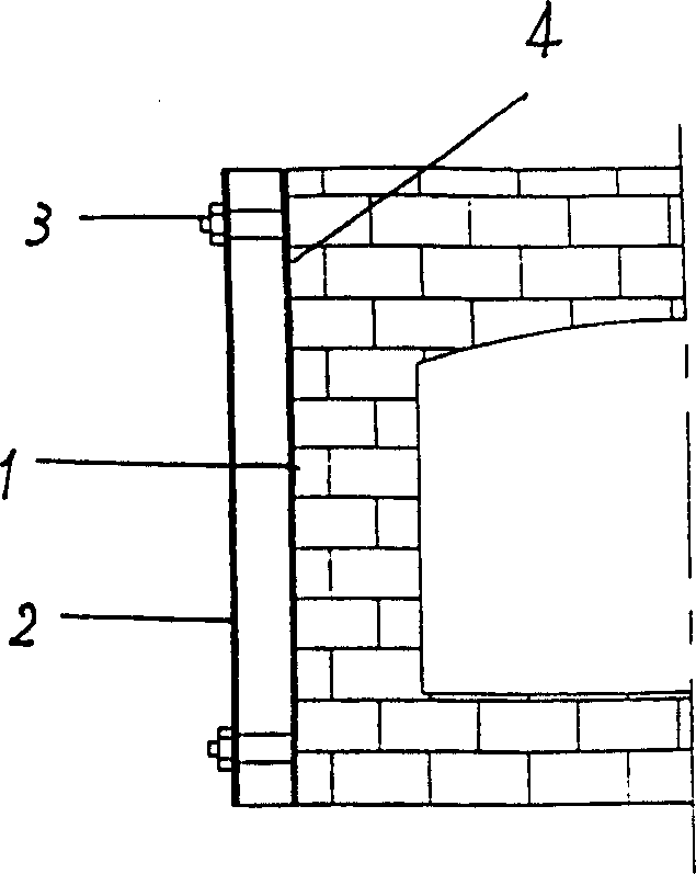
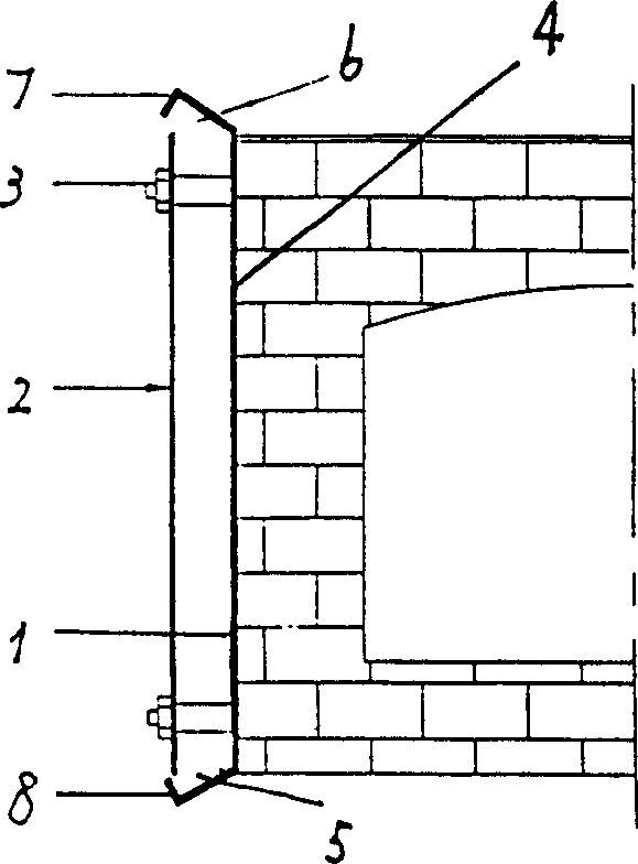
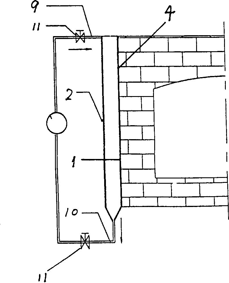
[0011] Such as figure 1 , figure 2 , image 3 As shown in Figure 4, the present invention adopts the method of double-layer furnace shell structure, and a layer of thin steel plate or aluminum plate 2 is installed outside the furnace shell 1, and the closed air layer formed increases the thermal resistance, forming a double-layer furnace shell, two layers The bolts 3 of the porcelain tubes or other methods can be used to connect between them, the surface temperature of the furnace is further reduced to reduce heat loss, and a layer of refractory fiber 4 can also be pasted on the inside or outside of the double-layer furnace shell, and the effect is better. Movable cover plates 7, 8 are installed on the bottom 5 and the top 6 of the double-layer furnace shell. When heating and heat preservation, the upper cover 7 and the lower cover 8 are closed, and the double-layer furnace shell forms a closed air layer to reduce heat loss. Open the upper and lower covers 7 and 8 during co...


PUM


Abstract

A mehod for decreasing the heat loss of industrial furnace shell features use of dual-layer furnace shell, that is, an additional shell made of thin steel or aluminium sheet is used outside exisiting shell to form an enclosed air layer, so increasing thermal resistance. A layer of refractory fibres is attached to internal or external surface of dual-layer furnace shell.

Description

technical field [0001] The patent of the invention relates to a method for reducing the heat loss of an industrial furnace, especially a method for reducing the heat loss of an industrial furnace shell, which belongs to the field of metallurgical industrial furnace design. Background technique [0002] Industrial furnaces are widely used in industries such as metallurgy, casting, heat treatment and forging. Its energy consumption accounts for more than 80% of the thermal processing professional factory. Improving the thermal efficiency of industrial furnaces, reducing energy consumption, and prolonging the life of furnaces are one of the focuses of industrial furnace research. In order to save energy, protect the environment, and effectively use existing resources, it is necessary to carry out energy-saving transformation of industrial furnaces. Generally, the industrial furnace is only covered with a layer of steel plate outside the furnace lining. In addition to protecti...

Claims


Application Information

Patent Timeline
IPC IPC(8): F27D1/00
Inventor 潘健生胡明娟余宁毛立忠
Owner SHANGHAI JIAO TONG UNIV
Why Eureka
Try Eureka