
Sensitization drum unit and image forming apparatus equipped therewith

A technology of photosensitive drum and toner image, applied in the field of image forming device and photosensitive drum unit, can solve the problem that the connecting claws cannot exert elastic force, etc., and achieve the effect of reliable conduction performance

Inactive Publication Date: 2008-08-13
KYOCERA DOCUMENT SOLUTIONS INC
View PDF2 Cites 6 Cited by
  • Summary
  • Abstract
  • Description
  • Claims
  • Application Information

AI Technical Summary

Problems solved by technology

[0010] However, only by setting the distance between the tips of the connecting claws to be only 1% larger than the inner diameter of the metal pipe, since the connecting claws are in an elastically bent state when the flange member is pressed into the metal pipe, sometimes the connecting claws are connected. Claws cannot exert elasticity
In this case, it is often difficult to reliably cut the inner peripheral surface of the metal pipe with the sharp end of the connecting claw
As a result, good conduction performance may not always be obtained

Method used


Image

  • Sensitization drum unit and image forming apparatus equipped therewith
  • Sensitization drum unit and image forming apparatus equipped therewith
  • Sensitization drum unit and image forming apparatus equipped therewith

Examples


Embodiment 1

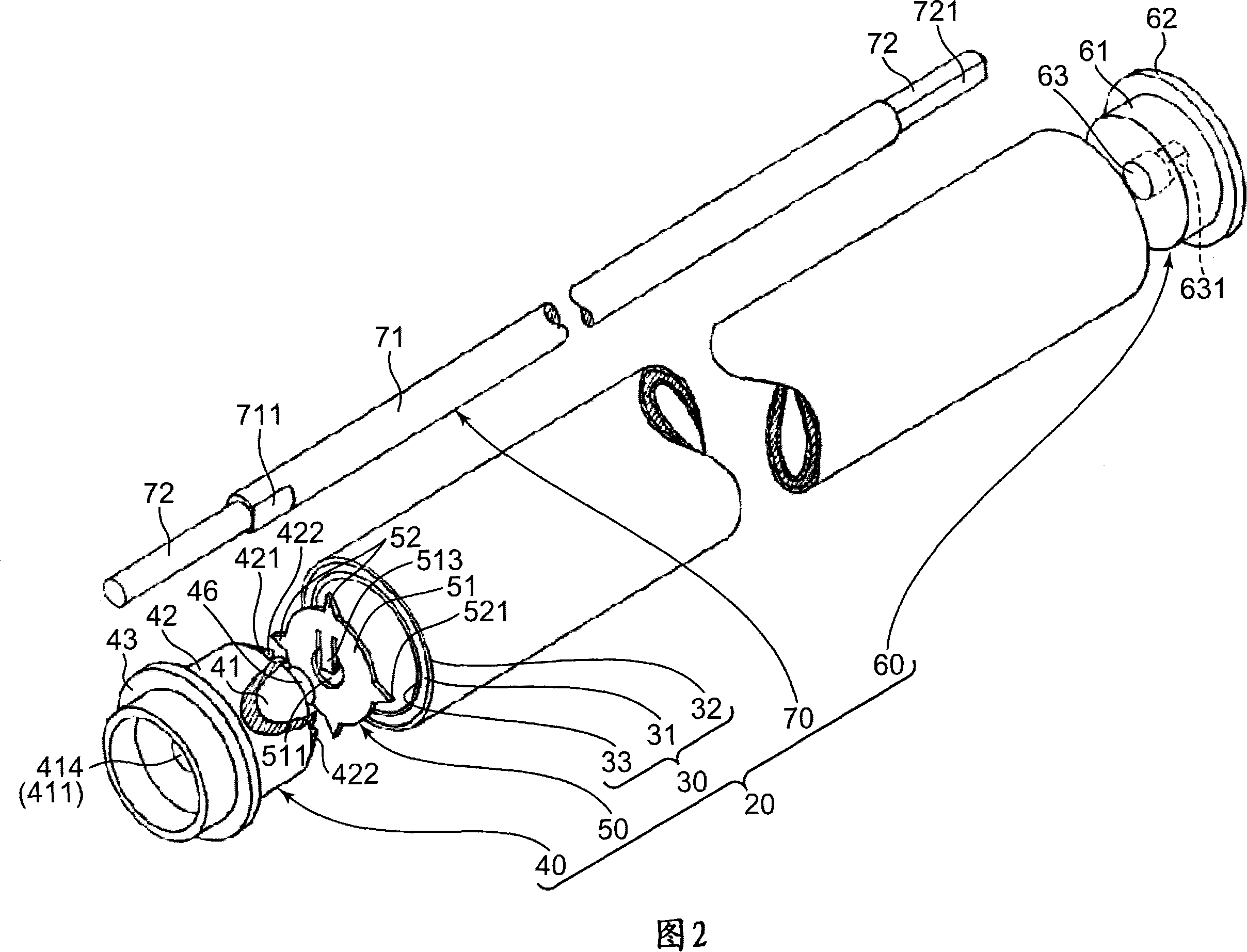
[0098] The ground plate 50 mounted on the photosensitive drum 30 having an outer diameter (D0 in FIG. 6A ) of 24 mm and an inner diameter of the metal tube 31 (D3 in FIG. The insulating coating 33 is 6 μm. When the ground plate 50 is installed in the photosensitive drum 30 through the flange member 40, the state where the photosensitive layer 32 is pressed against the inner peripheral surface of the photosensitive drum 30 is visually observed, and in order to confirm the The electrical connection state between the sharp end 521 of the connecting claw piece 52 and the inner peripheral surface of the metal pipe 31 was carried out a conduction test.

[0099] The condition of the ground plate 50 is as follows.

[0100] 1) The distance between the sharp ends 521 of the two connecting claws 52 radially facing each other (D in FIG. 6A ): 24mm

[0101] 2) Thickness dimension of ground plate main body 51: 0.25mm

[0102] 3) The outer diameter of the ground plate main body 51 (D2 in F...

Embodiment 2

[0117] With respect to the ground plate 50 shown in Example 1, an experiment was conducted to study the relationship between the calculated bending angle θ of the connection claw piece 52 and the depth of the flaw on the metal pipe 31 caused by the connection claw piece 52 . In this test, the outer diameter dimension D2 of the ground plate 50 was changed in order to vary the calculated bending angle θ of the connection claw piece 52 in various ways.

[0118] The flange member 40 mounted with the grounding plate 50 having the bending point 412 corresponding to each bending angle θ was inserted into the photosensitive drum 30, and at this time, a three-dimensional interference microscope (manufactured by Japan Veeco Instruments Inc.) Model Wyko-NT-1100) measure the depth of the scar formed by cutting the insulating coating 33 and the metal pipe 31 of the inner peripheral surface of the photosensitive drum 30 by the sharp end 521 of the connecting claw 52, ​​and measure the depth ...


PUM


Abstract

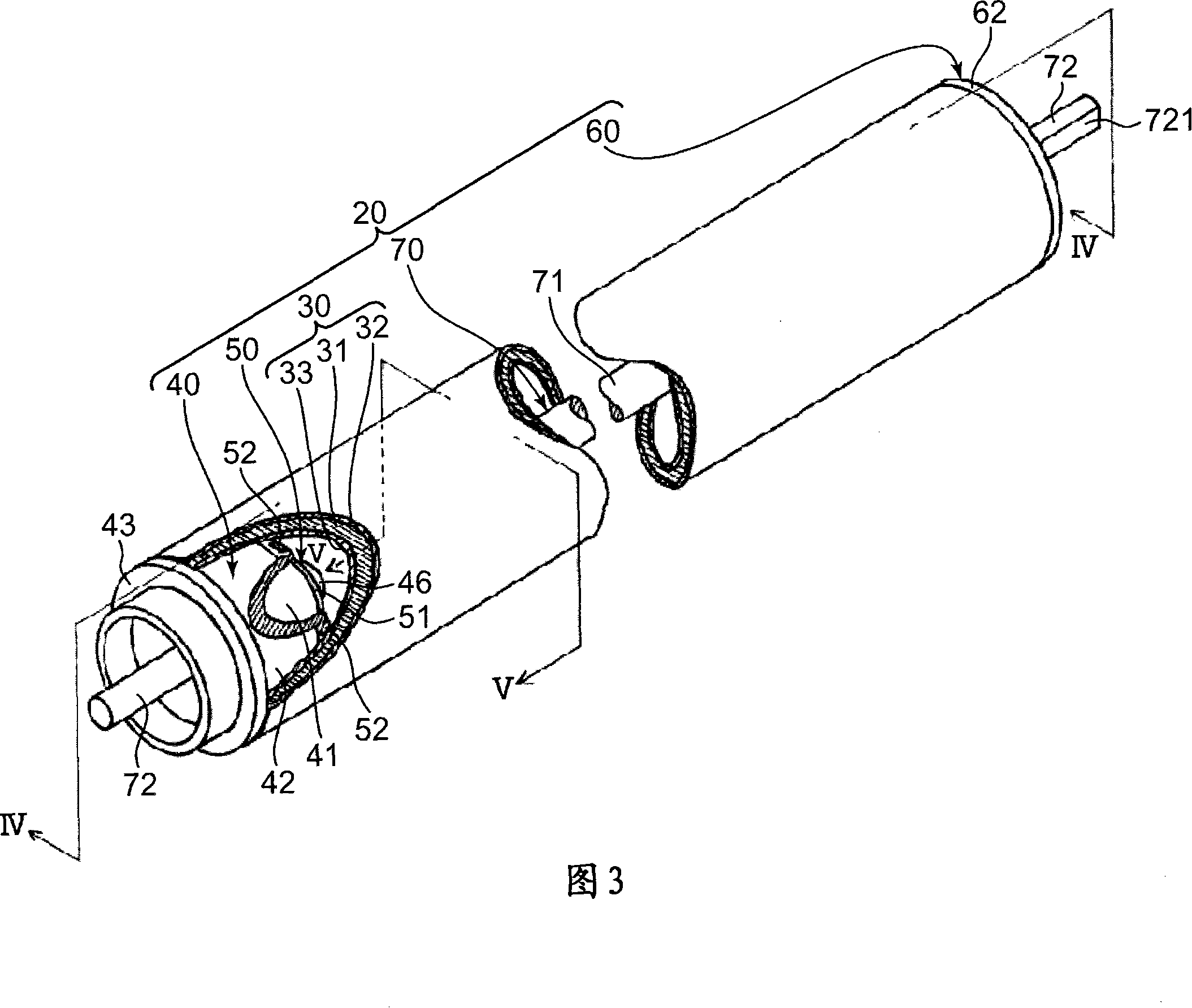
The invention provides a sensitization drum unit and an image forming device with the unit. The sensitization drum unit includes: a cylindrical-shaped metal tube provided with an outer circumferential surface and inner circumferential surface, wherein toner patterns are formed on the outer circumferential surface and an insulative film is laminated on the inner circumferential surface; a flange member mounted on an end of the metal tube; and a grounding plate mounted on the flange member and grounding charges on the metal tube. The grounding plate has a connection claw plate on the circumferential surface, the claw plate is bent to engage with the inner circumferential surface of the metal tube, thereby ensuring electrical connection with the metal tube, the flange member has an edge, and the bending of the connection claw is carried out about a support point defined by the edge, a calculational bending angle at which the connection claw plate is bent about the support point is set in the range of 10 to 45 degrees. In this way, the charges of the metal tube can be reliably grounded.

Description

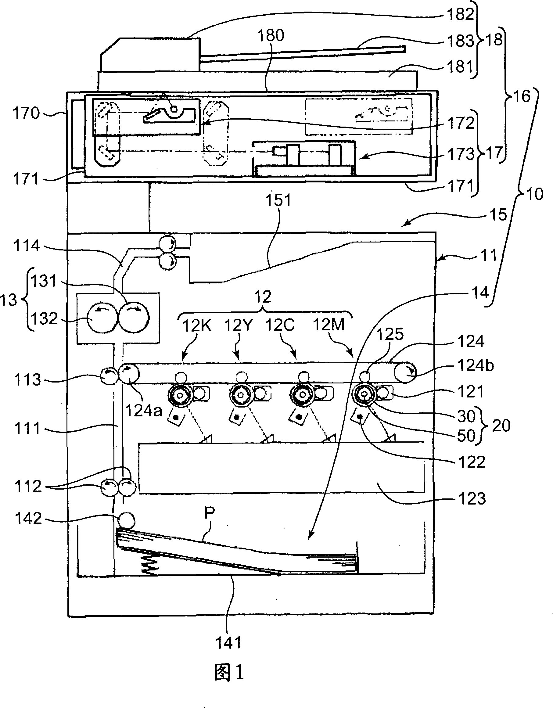
technical field [0001] The present invention relates to a photosensitive drum unit that forms a toner image based on image data, and an image forming apparatus including the photosensitive drum unit. Background technique [0002] Image forming devices such as copiers, printers, facsimile machines, etc., form an electrostatic latent image on the peripheral surface of a metal tube commonly known as a photosensitive drum by irradiating light based on image data read or transmitted from the outside, and the electrostatic latent image is transferred from the developing device to the image data. Toner is supplied on the latent image to form a toner image, which is then transferred to paper. By assembling such a metal tube and other necessary components into a unit, it is used as a photosensitive drum unit. [0003] As such a photosensitive drum unit, for example, a photosensitive drum unit described in Japanese Patent Laid-Open Publication No. 10-319783 (hereinafter referred to a...

Claims


Application Information

Patent Timeline
Patent Type & Authority Applications(China)
IPC IPC(8): G03G15/00
CPCG03G15/751
Inventor 渡边征正洼嶋志穗迫裕之浜崎一也斋藤荣
Owner KYOCERA DOCUMENT SOLUTIONS INC
Learn More