Making method for key light guide plate

A manufacturing method and technology of a light guide plate, applied to optical components, electrical components, electrical switches, etc., can solve problems such as slow production efficiency, inability to gather and refract light, and defects in light guide particles

Inactive Publication Date: 2008-08-13
ICHIA TECH
View PDF0 Cites 10 Cited by
  • Summary
  • Abstract
  • Description
  • Claims
  • Application Information

AI Technical Summary

Problems solved by technology

Because the traditional light guide plate with light guide particles is produced by inkjet technology, the resin injected by the inkjet head is directly molded on the carrier to form light guide particles. Since the inkjet head must move back and forth in the y-axis The resin can be sprayed on the carrier only when it is moving, which will cause slow production efficiency
[0006] The other is made by imprinting, which is rolling with a roller. The surface of the roller has a plurality of convex particles of light-guiding particles, and the roller is rolled on the surface or back of a

Method used


Image

  • Making method for key light guide plate
  • Making method for key light guide plate
  • Making method for key light guide plate

Examples


Embodiment Construction

[0046] The technical content and detailed description of the present invention are described as follows in conjunction with the accompanying drawings.

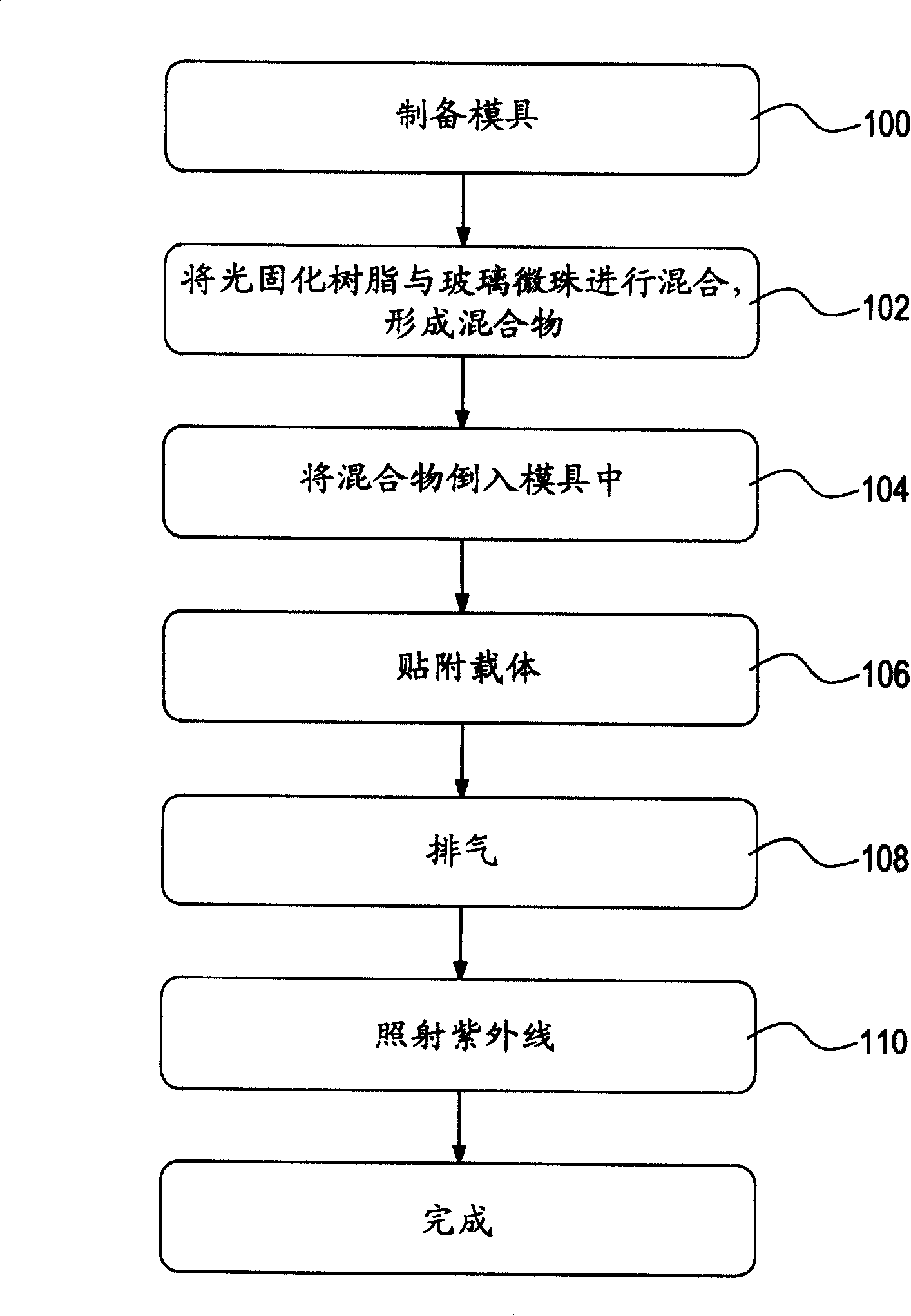
[0047] figure 1 It is a schematic diagram of the manufacturing process of the light guide plate of the present invention. As shown in the figure, this figure discloses a method for manufacturing a light guide plate used inside a keypad structure. First, a mold is prepared, such as step 100 .

[0048] Step 102, mixing the photocurable resin and the glass microspheres to form a mixture. In this figure, the photocurable resin is a UV curable resin.

[0049] Step 104, pour the mixture into the mold.

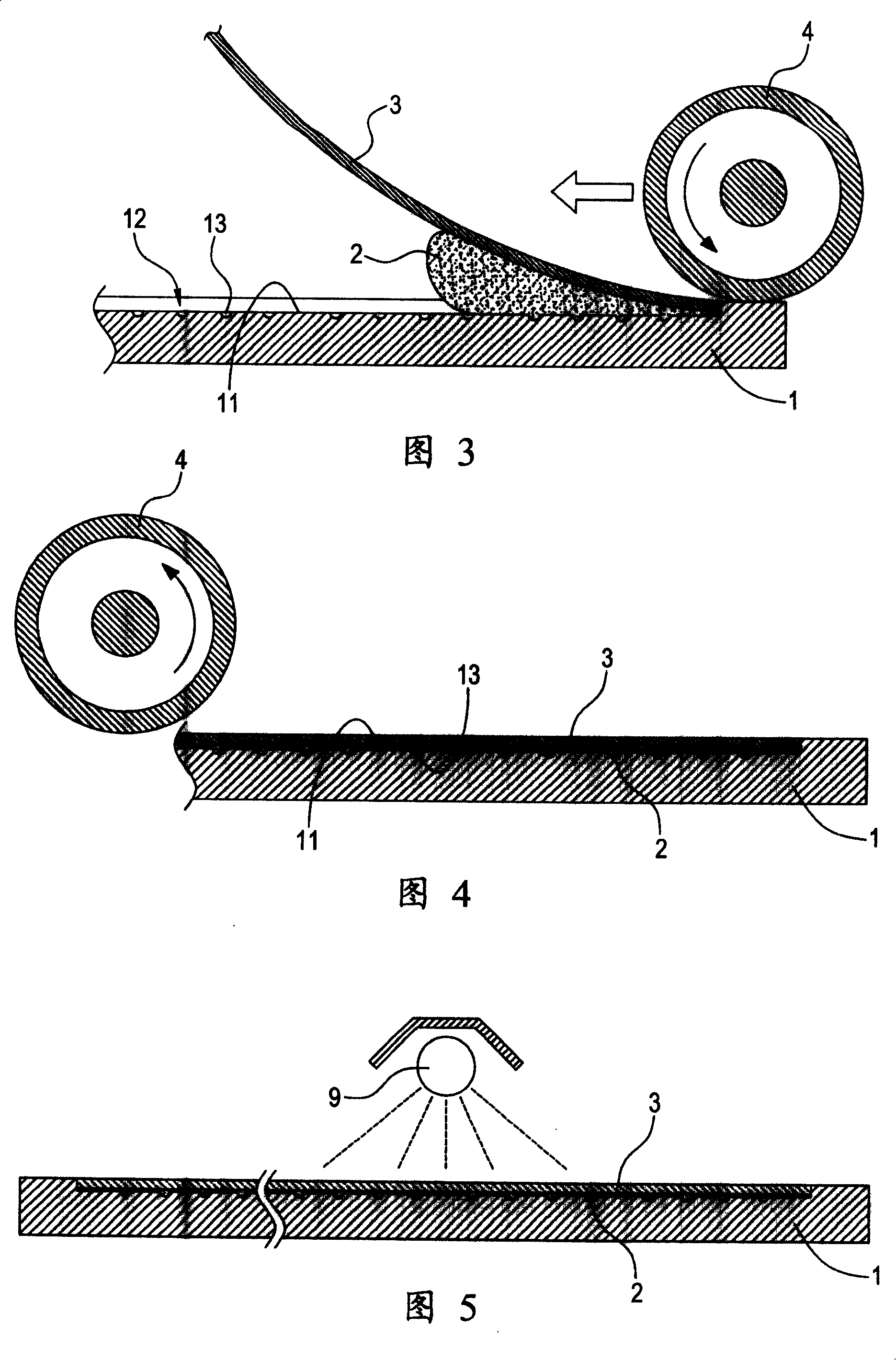
[0050] Step 106, attaching the carrier on the mixture. In this figure, the carrier is any one of transparent and colorless PC (polycarbonate) film or TPU (thermoplastic polyurethane) film.

[0051] Step 108 , use a rolling tool to roll on the surface of the carrier, so that the mixture can be evenly filled in the mold, and at th...


PUM


Abstract

The present invention provides a method for preparing a light conducting plate which is provided with a plurality of light conducting particles. The method comprises the following procedures: firstly preparing the mould which is provided with concave holes for molding a plurality of light conducing particles, decanting the mixture mixed by ultraviolet-curing resin and glass micro-bead into the mould, pasting the carrier on the mixture, rolling the surface of the carrier with a rolling instrument to uniformly filling the mixture in the mould, at the same time discharging the air among the mould, the carrier and the mixture, and at last when the ultraviolet-curing resin is executed with ultraviolet irradiation, solidifying the ultraviolet-curing resin on the carrier. Then the solidified resin is taken out from the mould thereby forming the light conducting plate with a plurality of light conducting particles.

Description

technical field [0001] The invention relates to a keypad structure, in particular to a manufacturing method of a light guide plate. Background technique [0002] The button structure is one of the main input devices of electronic devices. Each button on the button structure usually has corresponding numbers, characters, phonetic symbols, radicals of input methods and various functional graphics, etc., so that users can input data, Or perform various functions of the electronic device. Therefore, the key structure is an extremely important input device for electronic devices. [0003] Since the electronic device is in a well-lit environment, the user can clearly see the position of each button, and problems such as pressing the wrong button will not occur during operation and pressing. If there is no light or insufficient light, it is difficult for the user to operate the buttons on the electronic device. Therefore, the inner layer of the button structure is equipped with ...

Claims


Application Information

Patent Timeline
IPC IPC(8): H01H11/00H01H13/88H01H13/02G02B5/02B29D11/00
Inventor 许志和张建利
Owner ICHIA TECH
Why Eureka
Try Eureka