Electronic equipment and key lights

A technology of electronic equipment and keys, applied in the direction of circuits, electric switches, electrical components, etc., can solve the problems of occupying vertical space and low utilization rate of key light, so as to reduce vertical space, improve light utilization rate, and improve light guide utilization rate Effect

Active Publication Date: 2020-03-24
VIVO MOBILE COMM CO LTD
View PDF9 Cites 0 Cited by
  • Summary
  • Abstract
  • Description
  • Claims
  • Application Information

AI Technical Summary

Problems solved by technology

[0004] The invention provides a key light to solve the problems of low light utilization rate and vertical space occupation of the key light of the current electronic equipment

Method used


Image

  • Electronic equipment and key lights
  • Electronic equipment and key lights
  • Electronic equipment and key lights

Examples


Embodiment Construction

[0030] In order to make the purpose, technical solution and advantages of the present invention clearer, the technical solution of the present invention will be clearly and completely described below in conjunction with specific embodiments of the present invention and corresponding drawings. Apparently, the described embodiments are only some of the embodiments of the present invention, but not all of them. Based on the embodiments of the present invention, all other embodiments obtained by persons of ordinary skill in the art without making creative efforts belong to the protection scope of the present invention.

[0031] The technical solutions provided by various embodiments of the present invention will be described in detail below in conjunction with the accompanying drawings.

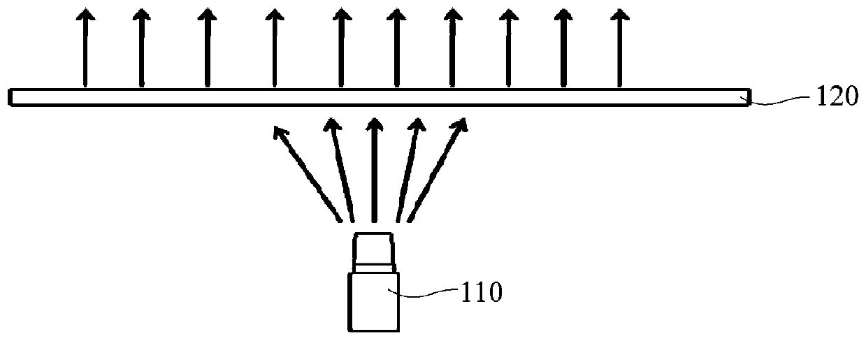
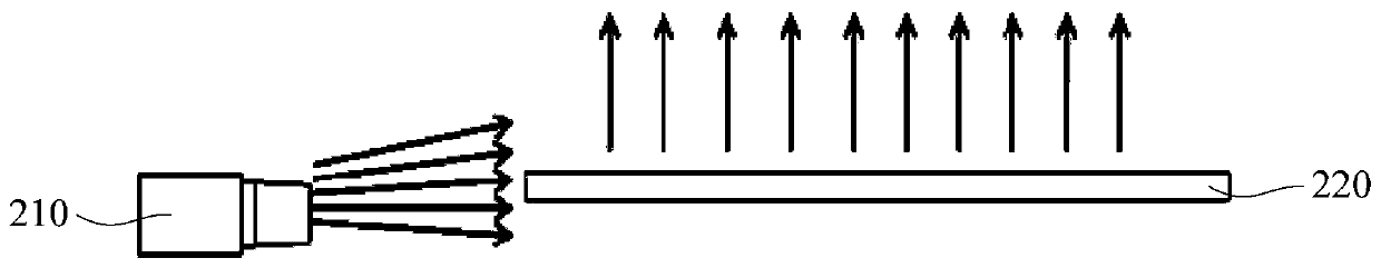
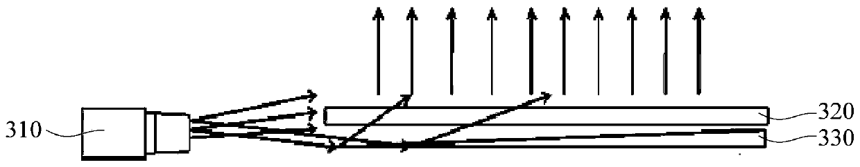
[0032] The embodiment of the present invention discloses a key light. The disclosed key light includes a light-emitting module and a light guide layer for guiding the light projected by the light...


PUM


Abstract

The invention discloses a key lamp, which comprises a light emitting module and a light guiding layer used for guiding light rays projected by the light emitting module onto a key body of the key lamp, wherein the light emitting module is arranged on one side of the light guiding layer. The key lamp further comprises a light collecting member, wherein the light collecting member is disposed on thelight incident side of the light guiding layer, and is used for collecting the light rays onto the light guiding layer. The light projection direction of the light emitting module is parallel to thelight guiding layer. The invention further discloses electronic equipment. The electronic equipment and the key lamp can solve the problems that a key lamp of the existing electronic equipment has lowlight utilization rate and occupies vertical space.

Description

technical field [0001] The invention relates to the technical field of button lamp design, in particular to an electronic device and a button lamp. Background technique [0002] The key light is an important part of the electronic device, and the light projected by the key light can remind the user of the specific position of the key, thereby facilitating the user's operation. At the same time, the key light can play a role in decorating the electronic equipment, especially in a dark environment, the key light can make the electronic equipment more beautiful. [0003] At present, the button lamps of electronic equipment mainly include a direct light-emitting structure and a side-emitting light structure. Please refer to figure 1 , figure 1 It is a schematic diagram of a direct light emitting structure. In the direct light emitting structure, the light emitting module 110 is located below the light guide layer 120. This structure requires a large vertical space for the ele...

Claims


Application Information

Patent Timeline
Patent Type & Authority Patents(China)
IPC IPC(8): H01H13/02
CPCH01H13/023
Inventor 黄攀周万里刘明建叶玮
Owner VIVO MOBILE COMM CO LTD
Why Eureka
Try Eureka