Method and apparatus for ensuring minimum contrast in machine vision systems

A machine vision system, contrast technology, applied in stereo systems, lighting devices, instruments, etc., can solve the problems of lack of contrast and the inability of the vision system to detect objects.

Active Publication Date: 2017-07-28
ORMON CORP
View PDF5 Cites 0 Cited by
  • Summary
  • Abstract
  • Description
  • Claims
  • Application Information

AI Technical Summary

Problems solved by technology

Therefore, in some special cases, the vision system will not be able to detect the object due to the lack of contrast

Method used


Image

  • Method and apparatus for ensuring minimum contrast in machine vision systems
  • Method and apparatus for ensuring minimum contrast in machine vision systems
  • Method and apparatus for ensuring minimum contrast in machine vision systems

Examples


Embodiment Construction

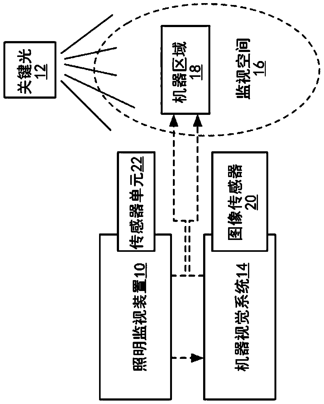
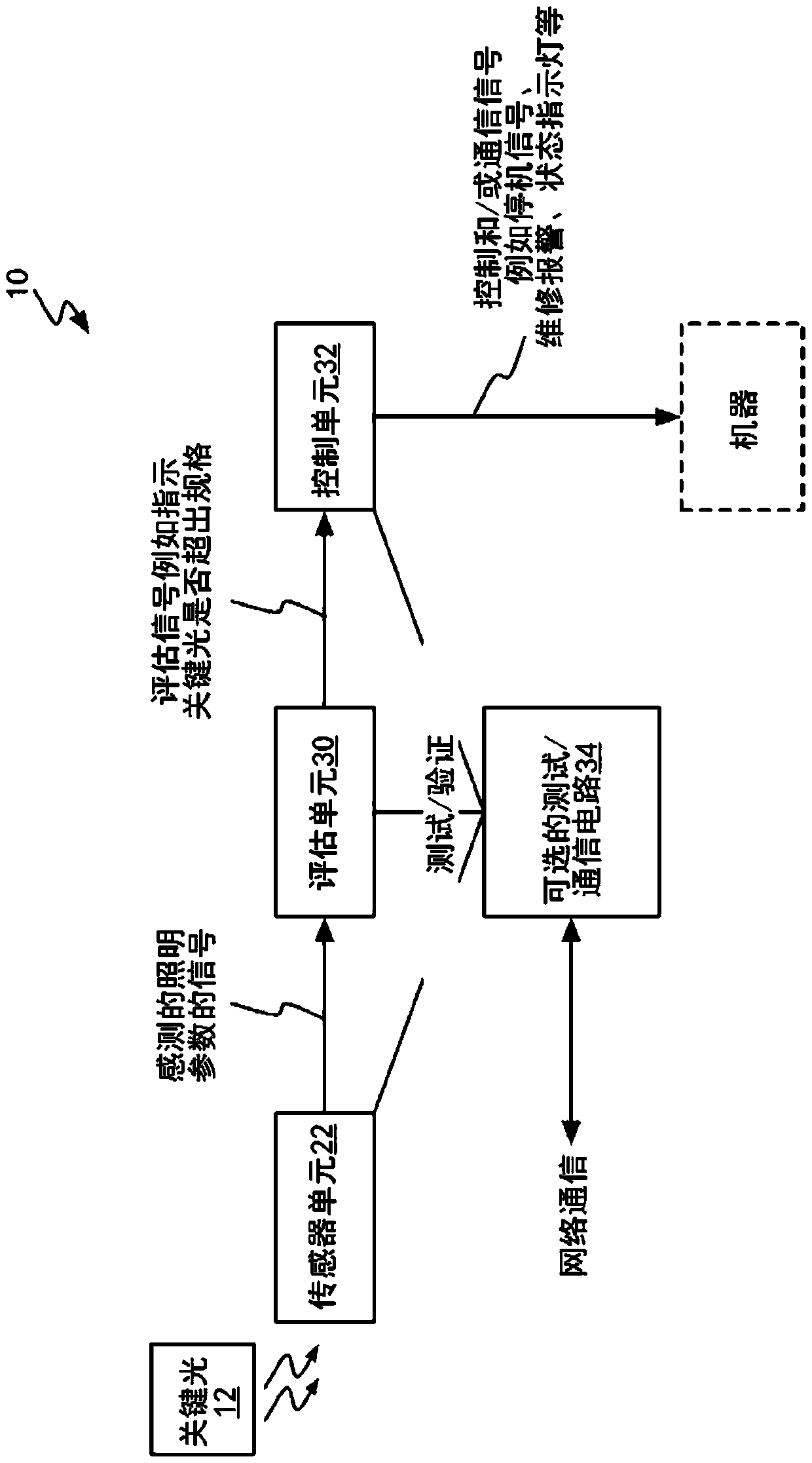
[0020] The present disclosure provides beneficial teaching in several areas, including: (1) lighting arrangements for assuring contrast of objects; (2) methods and apparatus for monitoring lighting conditions; and (3) methods for measuring contrast and device. These and other advantages can be achieved at least by means of figure 1 The configuration and operation of the lighting monitoring device 10 of the illustrated example are implemented in part.

[0021] The illumination monitoring apparatus 10, in one or more embodiments, is configured to monitor an illumination source used as a key light 12, wherein the illumination from the key light 12 enhances object contrast within the field of view of the machine vision system 14 . This field of view defines a surveillance area or space 16, collectively referred to as "surveillance space 16." In a non-limiting example, the surveillance space 16 may be understood as an area or area surrounding a hazardous machine or area 18 where...


PUM


Abstract

In one aspect, the present disclosure provides a method and apparatus for verifying that minimum object contrast requirements are met within an area representing a space to be monitored by a machine vision system. In a complementary manner, the present disclosure also provides a method for restricting the location of light sources for illuminating a surveillance space to a minimum height above ground, and for the use of key lights that are provided in conjunction with the Asymmetric lighting within a surveillance space relative to cameras imaging that surveillance space. Accordingly, the present disclosure also provides a method and apparatus for monitoring proper operation of critical lights and responding to improper operation. Minimum contrast verification and critical light monitoring operations can be accomplished using stand-alone devices, or can be incorporated into a machine vision system.

Description

[0001] This application claims priority to US Provisional Application 61 / 646,491, filed May 14, 2012. technical field [0002] The invention relates to an image-based (machine vision) monitoring system, for example for protecting machines. Background technique [0003] In general, vision systems rely on the contrast of pixel brightness to detect objects. This contrast can be caused by the texture of the object, a different color between the object and the background, or shadows on the surface of the object, among others. Without making certain assumptions, there is no guarantee of contrast, since the object may not have any texture on it, its color may be similar to that of the background, or depending on its shape and / or lighting conditions, there may be no shadows. Therefore, in some special cases, the vision system will not be able to detect the object due to the lack of contrast. This problem becomes especially noticeable when the visual surveillance system is applied...

Claims


Application Information

Patent Timeline
Patent Type & Authority Patents(China)
IPC IPC(8): G06T7/00G06T1/00H05B37/02H04N13/239
CPCG06T7/0002G06T2207/10028G06T2207/30168G06T2207/30204G06T1/0007H04N13/243H04N13/239H05B47/11Y02B20/40G09G1/002H04N13/271
Inventor 木下航一阿姆布里什·特亚吉约翰·德林卡尔德谷喜东
Owner ORMON CORP
Why Eureka
Try Eureka